


ADCP-80-412 Issue 1 April 2000
Page 3
© 2000, ADC Telecommunications, Inc.
1 PRODUCT DESCRIPTION
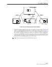
Electronic circuitry in the Bay Tracer sensor checks for a change in current on one or more
–48 Vdc power conductors on the DSX-1 or DSX-3 fuse panel caused by an individual jack
insertion on the far end bay and uses this change to activate an LED. The change in current is
detected by a clamp-on inductive pick-up coil encircling the –48 Vdc power conductor(s)
attached to the DSX fuse panel of the device being monitored. A two-conductor 8-foot (20.32
cm) trailing sensor cable attached to the inductive pick-up coil is used to transmit a signal to the
sensor. A customer supplied two-conductor (–48 Vdc and battery return) power cable is used to
transmit power from the fuse panel on the back of the DSX-1 or DSX-3 bay to the sensor.
2 SPECIFICATIONS
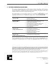
Bay Tracer Illuminator specifications are provided in Table 1.
Table 1. Bay Tracer Illuminator
PARAMETER SPECIFICATION
Electrical Specification
Power
Voltage –36 Vdc to –75 Vdc
Current Consumption 40mA (maximum) @ –48Vdc
Sensor Interface Two conductor cable with screw connections, 22 AWG
Light Indicator Off: normal, On: bay current change detected
LED Flashing Rate 4 Hz
Power Interface Two conductor screw connections for –48 Vdc, and battery return,
18-20 AWG
Heat Dissipation 0.96 W (nominal)
Fusing 0.5A GMT type (customer provided at DSX fuse panel)
Mechanical Specification
Weight 1.2 lb (5.44 g)
Operating Environment
Non-Operating
23° F to 131° F (–5° to 55°C), up to 80% Relative Humidity
–40° F to 185° F (–40° C to 85° C), up to 95% Relative Humidity
Sensor Dimensions (H
W D) 1.75 in. (4.45 cm) 4.25 in. (10.8 cm) 3 in. (7.62 cm)
Coil Dimensions (H W D)
2.1 in. (5.3 cm) 2.0 in. (5.1 cm) 0.610 in. (1.55 cm)
3/4-in. opening
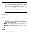
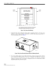
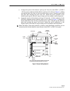
3 INSTALLATION
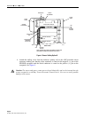
The ADC Bay Tracer Electronic Sensor is designed to be installed on the top cross-member or
left/right vertical support flanges of the bay. The sensor and power cabling for the device must
be routed over the top of the bay as shown in Figure 1.