


ADCP-80-412 Issue 1 April 2000
Page 7
© 2000, ADC Telecommunications, Inc.
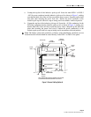
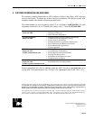
TOP VIEW
FRONT VIEWLEFT SIDE VIEW RIGHT SIDE VIEW
POWER
CONNECTOR
SENSOR
CONNECTOR
RED
FLASHING
LED
13928-B
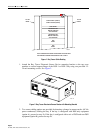
Figure 5. Bay Tracer Electronic Sensor Device Connectors
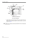
5. Attach the customer-supplied power feed wires for the electronic sensor device to an
unused –48 Vdc branch circuit on the DSX-1 or DSX-3 fuse panel as shown in Figures 3
and 4. Attach the opposite ends of these wires to the ADC-provided power connector on
the electronic sensor device making sure that the wire supplying –48 Vdc is routed to the
–48V pin on the POWER receptacle and the battery return wire is routed to the RET pin
on the receptacle. See Figure 5. A reverse blocking diode is incorporated into the electronic
sensor device to prevent damage from a power lead reversal.
Note
: The fuse panel branch circuit should be fused at 0.5 A.