


ADCP-80-412 Issue 1 April 2000
Page 6
© 2000, ADC Telecommunications, Inc.
FILLER
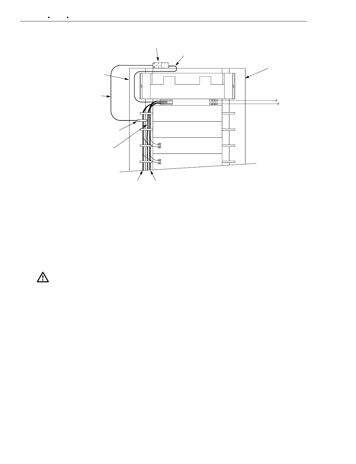
PANEL
SENSOR
ATTACHMENT
INDUCTION
COIL
KEEP NON-DSX
EQUIPMENT
OUT OF COIL
UPPER CABLE TROUGH
POWER
ATTACHMENT
BAYTRACER
FILLER
PANEL
—48V
—48V
BATTERY
RETURN
BATTERY
RETURN
FUSE PANEL
DSX
PANEL
DSX
PANEL
BATTERY RETURN
—48V
BATTERY RETURN
—48V
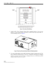
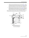
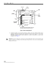
REAR VIEW
NOTE: SENSOR AND POWER ATTACHMENT POSITION AND
APPEARANCE SHOWN EXAGGERATED FOR CLARITY.
14059-A
Figure 4. Sensor Cabling Option B
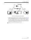
4. Attach the trailing wires from the inductive pickup coil to the ADC-provided sensor
connector making sure that the white conductor is routed to the negative (–) pin on the
SENSOR receptacle and the black conductor is routed to the positive (+) pin on the
receptacle. See Figure 5.
Caution
:
The sensor and power connectors are keyed identically and can be inserted into the
wrong receptacles on the Bay Tracer Electronic Sensor Device. Use care to avoid possible
damage to the sensor.