


ADCP-80-412 Issue 1 April 2000
Page 4
© 2000, ADC Telecommunications, Inc.
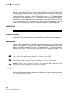
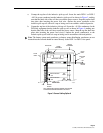
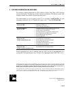
BLANK PANEL (FRONT)
CABLE TROUGH (REAR)
FUSE PANEL
RESERVED FOR
MISCELLANEOUS
APPLICATIONS
RESERVED FOR
MISCELLANEOUS
APPLICATIONS
DSX
PANEL
DSX
PANEL
14093-A
FILLER
PANEL
FILLER
PANEL
NOTE: SENSOR AND POWER ATTACHMENT POSITION AND
APPEARANCE SHOWN EXAGGERATED FOR CLARITY.
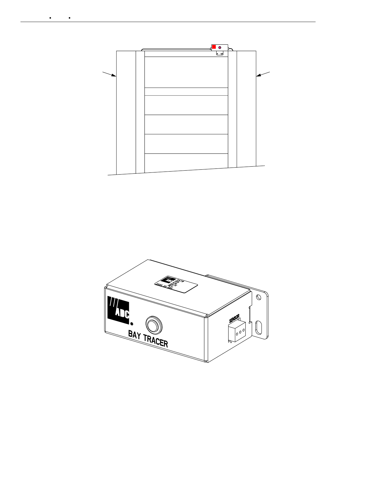
Figure 1. Bay Tracer Cable Routing
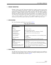
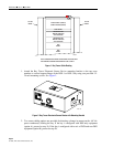
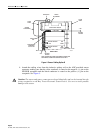
1. Attach the Bay Tracer Electronic Sensor Device mounting bracket to the top cross
member or vertical support flange of the DSX-1 or DSX-3 bay using two provided 12–
24 rack mounting-screws. See Figure 2.
14001-B
Figure 2. Bay Tracer Electronic Sensor Device with Mounting Bracket
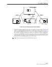
2. Two sensor cabling options are provided for detecting a change in current on the –48 Vdc
power conductor(s) feeding the bay. If the bay is configured with DSX-only equipment
(option A), proceed to step 2a. If the bay is configured with a mix of DSX and non-DSX
equipment (option B), proceed to step 2b.