


ADCP-80-412 Issue 1 April 2000
Page 5
© 2000, ADC Telecommunications, Inc.
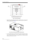
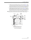
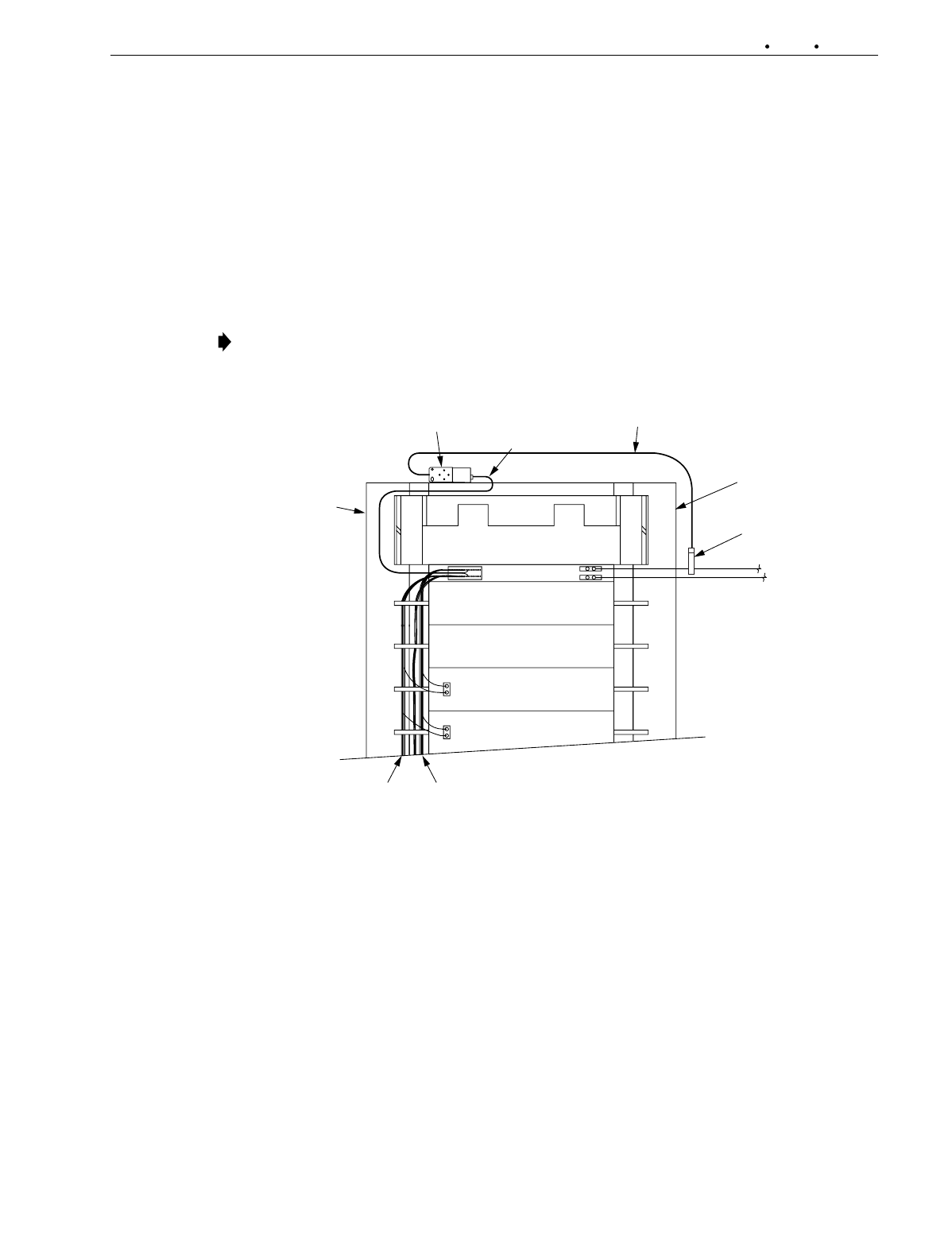
a. Unsnap the top bar of the inductive pick-up coil. Insert the main DSX-1 or DSX-3
–48 Vdc power conductor into the inductive pick-up coil as shown in Figure 3, making
sure that the label side of the coil faces toward the power source. Snap the top bar back
into place after inserting the power feed wire. Anchor the power conductor to the
inductive pick-up coil with a tie wrap or lacing cord in accordance with local practice.
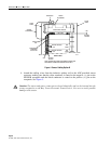
b. Unsnap the top bar of the inductive pick-up coil. Insert the –48 Vdc conductors for the
DSX-only equipment into the inductive pick-up coil as shown in Figure 4, making sure
that the label side of the coil faces toward the power source. Snap the top bar back into
place after inserting the power feed wire(s). Anchor the power conductor(s) to the
inductive pick-up coil with a tie wrap or lacing cord in accordance with local practice.
Note
: The battery return main conductor, or battery return distribution conductors are not
inserted into the coil and should be routed directly to the DSX-1 or DSX-3 fuse panel.
FILLER
PANEL
SENSOR
ATTACHMENT
INDUCTION
COIL
UPPER CABLE TROUGH
POWER
ATTACHMENT
BAYTRACER
FILLER
PANEL
—48V
—48V
BATTERY
RETURN
BATTERY
RETURN
FUSE PANEL
DSX
PANEL
DSX
PANEL
BATTERY RETURN
—48V
BATTERY RETURN
—48V
REAR VIEW
NOTE: SENSOR AND POWER ATTACHMENT POSITION AND
APPEARANCE SHOWN EXAGGERATED FOR CLARITY.
14088-A
Figure 3. Sensor Cabling Option A