125
B
Blank Front Panel Option 001
Introduction
This appendix describes the blank front panel option (Option 001) for the Agilent 6030A/31A/32A power supplies. Option
001 is designed for applications in which front panel operation and monitoring are unnecessary. It has no front-panel
controls and indicators except for the LINE switch and OVP ADJUST control found on the standard unit, and a pilot light
to indicate when ac input power is turned on. All other characteristics of the standard are retained.
Except for references to front-panel controls and indicators, most of the information in the manual applies to Option 001
units. No attempt has been made in this appendix to change every reference to front-panel controls and indicators. In
general, information in this appendix replaces only those procedures whose modification may not be obvious to the user.
When reading the manual, the user can usually skip over references to front-panel controls and indicators other than the
LINE switch and OVP ADJUST control.
Troubleshooting
The major difference between troubleshooting an Option 001 unit and a standard power supply is that the front panel is not
available to help you isolate the problem to a specific section in the power supply. If you know which section of the supply
is defective, simply go to that section in the troubleshooting procedure and troubleshoot as described in Chapter 3.
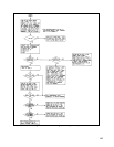
To help you isolate the problem to a specific area of the supply, use the flowchart provided in this section.
If you cannot isolate the problem using the flowchart, you could replace the blank front panel of your supply with a standard
front panel and then troubleshoot the unit. Part numbers for front panel assemblies are provided in Chapter 5.
Chapter 2 Manual Changes:
On Page 20 Power Limit Calibration, change step f to read: Connect a DVM to control board test connector A2J7 pin 16
(CC). Observe the DVM while adjusting A2R25 (POWER LIMIT) clockwise. Stop adjusting as soon as test point A2J7-16
goes from high to low.
Note: You can also send an STS? query (or SCPI equivalent) in a looping program and monitor when the power
supply status changes to CC mode.
Under the Performance Tests section, any references to front panel control will have to be accomplished using GPIB
commands. Use the following guidelines:
1.
To set the voltage and current to specific values, use the VSET and ISET (or SCPI equivalent) commands.
2. If the procedure says to check the CC or CV LED's, use an STS? query (or SCPI equivalent). A returned value of 1
indicates CV mode; a value of 2 indicates CC mode.


