62
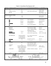
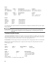
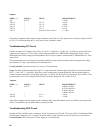
Outputs:
NODE ( + ) NODE (-) SETUP MEASUREMENT
VM A2J7-4 3.75Vdc
A2U5-1 " VP = 0 -14Vdc
A2U3-6 " VP = 0 -14Vdc
A2U5-1 " VP = 5 4.7Vdc
A2U3-6 " VP = 5 5.1Vdc
A2U5-7 " short A2J7-24 to A2U5-5 + 7.5Vdc
If the failure symptoms include output voltage oscillation, check if the CV Error Amp circuit is at fault by shorting A2U3-6
to A2U3-2. If oscillations stop, the CV Error Amp circuit is probably at fault.
Troubleshooting CC Circuit
I-MON, the output of CC Monitor Amp A2U1, in volts is 5/17 (6030A); 1/24 (6031A); 1/10 (6032A); equals (6035A) the
output current in amperes. CC Error Amp A2U4C compares l-MON to CC PROGRAM. Differentiator circuit A2U4A
differentiates the inboard voltage sense and stabilizes the CC loop. Its output is summed with CC PROGRAM at CC Error
Amp A2U4C.
The measurements below verify that the operational amplifier circuits provide expected positive and negative dc voltage
gain when the CC loop is open and the power mesh shut down.
Circuits Included. Constant Current (CC) Circuit on A2 control board.
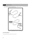
Setup. The Main Troubleshooting Setup, Page 53, except connect the external supply with polarity reversed to the unit's +
OUT ( - ) and - OUT ( + ) terminals. Apply the ac mains voltage to the isolation transformer. Set the external supply to
3.0Adc constant current with a voltage limit in the range 5 to 20Vdc. Set IP to 0Vdc by connecting to P or set IP to +5Vdc
by connecting to A2J7-24 according to SETUP below. Set mode switches B1, B2, and B3 AU to 0.
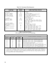
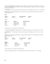
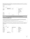
Outputs:
NODE ( + ) NODE (-) SETUP MEASUREMENT
IM A2J7-4 0.88Vdc (6030A)
0.125Vdc (6031A)
0.30Vdc (6032A)
1.00Vdc (6035A)
A2U4-8 " IP = 0 -14Vdc
A2U4-8 " IP = 5 +14Vdc
If the failure symptoms include output current oscillation, check if the differentiator circuit is at fault by removing resistor
A2R35. If oscillations stop, the differentiator is probably at fault.
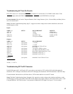
Troubleshooting OVP Circuit
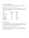
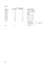
Flip-flop A2U8A-A2U8D is set by comparator A2U8C and reset by OV CLEAR. TTL low at A2U18-12 inhibits the PWM.
OVP Program Voltage on A2J7-7 is equal to Eout/250 (6035A), Eout/100 (6030A), Eout/30 (6032A), Eout/10 (6031A).
Circuit included. OVP Circuit and 2.5V bias supply on A2 control board.


