61
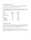
Troubleshooting Down Programmer
The down programmer discharges the output when either PWM OFF is generated or CV ERROR is more negative than
about - 3Vdc. Comparator A5U1 triggers down programming when the voltage at A5U1-5 is less than about 4Vdc.
Circuit Included. Down programmer and 10.6V bias supply on A1 main board.
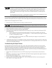
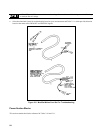
Setup. The Main Troubleshooting Setup, Page 53, except connect the external supply to the unit's + OUT ( + ) and - OUT (
- ) terminals. Apply the ac mains voltage to the isolation transformer. Set the external supply for an output voltage of 10Vdc
and set current limit for 2.5 Amps. Set the power supply under test for a voltage setting of 8.0Vdc and current setting of
2.0Adc using the ''DISPLAY SETTING" switch.
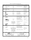
Outputs:
NODE ( + ) * EXTERNAL SUPPLY MEASUREMENT
A5C1 ( + ) C3(6031A) ON/OFF 10Vdc
A5VR1(K) ON/OFF 6.5Vdc
A5U1-3 ON/OFF 0.2Vdc
A5CR1( K ) CR2(6031A) OFF 0.6Vdc
A5CR1( K ) CR2(6031A) ON 0.2Vdc
A5U1-1 OFF 0.5Vdc
A5U1-1 ON 5.0Vdc
A5R20 + (6030A/35) OFF < 0.001Vdc
A5R20 + (6030A/35) ON 1.5Vdc
across A5R1(6031A) OFF < 0.001Vdc
across A5R1(6031A) ON 0.10Vdc
across A5R14(6032A) OFF < 0.001Vdc
across A5R14(6032A) ON 0.17Vdc
* NODE (-) = A2J7-4
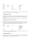
Troubleshooting CV Circuit
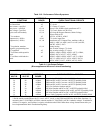
V-MON, the output of CV Monitor Amp A2U2. is 1/40 (6030A); 1/4 (6031A); 1/12 (6032A); l/l00 (6035A) the voltage
between + S and - S. CV Error Amp A2U3 compares V-MON to CV PROGRAM. Innerloop Amp A2U5A stabilizes the
CV loop with input from A2U5B. The measurements below verify that the operational amplifier circuits provide expected
positive and negative dc voltage excursion when the CV loop is open and the power mesh shut down.
Circuits Included. Constant Voltage (CV) Circuit and buffer amplifier A2U5B.
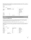
Setup. The Main Troubleshooting Setup, Page 53. Apply the ac mains voltage to the isolation bias transformer, and
disconnect the external supply. Remove the + S jumper and connect A2J7-2 ( +15V) to + S. Set mode switch settings B4,
B5 and B6 all to 0. Set VP to 0Vdc by connecting to P or set VP to + 5Vdc by connecting to A2J7-24 according to SETUP
below. VP and P are on rear-panel terminal block.


