15
Maintenance described herein is performed with power supplied to the instrument, and protective covers
removed. Such maintenance should be performed only by service trained personnel who are aware of the
hazards involved (for example, fire and electrical shock). Where maintenance can be performed without
power applied, the power should be removed.
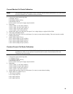
Voltage Monitor Zero Calibration
a. Send string "VSET 0; ISET 0; OUT OFF".
b. Short power supply output terminals.
c. Attach the DVM from
M on the rear panel through a 1kΩ resistor to A2J7 pin 3 (V-MON buffered).
d. Adjust A2R22 (V-MON ZERO) to 0V ±20µV. ( ± 40µV 6035A).
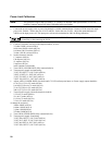
Common Mode Calibration
a. Send string ''VSET 0; ISET 0; OUT OFF".
b. Short power supply sense terminals ( + S to - S) at rear panel.
c. Attach the DVM from
M on the rear panel through a 1kΩ resistor to A2J7 pin 3 (V-MON buffered).
d. Take initial reading from DVM.
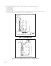
e. Remove both local sensing straps from rear-panel terminal block, and connect a 1-volt external power supply with its +
lead to - S and its--lead to - Out. See Figure 2-1.
f. Adjust A2R21 (CV LOAD REG) to Initial Reading
±20µV (6030A)
±80µV (6031A)
±20µV (6032A)
±40µV (6035A)
g. Replace local sense straps after removing external power supply.
Note: Common mode calibration is not required for Agilent Model 6035A.
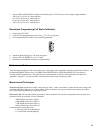
Remote Readback Zero Calibration
Note:
This procedure and the following three procedures must be done as a set, without omitting any of the four
procedures. Also, the following four procedures require that V-MON ZERO (A2R22) be adjusted within
specifications. If it is not, perform the Voltage Monitor Zero Calibration before proceeding.
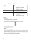
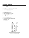
a. Connect an external supply to the power supply as shown in Figure 2-2.
b. Send string "VSET 0; ISET 5; OUT ON''.
c. Attach the DVM from
M on the rear panel through a 1KΩ resistor to A2J7 pin 3 (V-MON buffered).
d. Adjust A8R40 (CV PROG ZERO) to 625µV ± 30µV.
e. Remove the DVM.
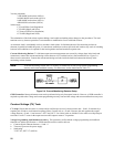
f. Enter and run the following program and begin noting the controller's display:
10 OUTPUT 705; "VOUT''
20 ENTER 705; A
30 DISP A
40 GOTO 10
50 END


