


Chapter 7 Tutorial
Connecting the Load
147
7
Connecting the Load
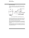
Output Isolation
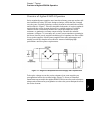
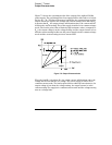
The output of the power supply is isolated from chassis ground. Any output
terminal may be grounded, or an external voltage source may be connected
between any terminal output and ground. However, output terminals must be
kept within ±60 Vdc when metal shorting bars without insulation are used to
connect the (+) output to the (+) sense and the (-) output and the (-) sense
terminals or ±240 Vdc of ground when metal shorting bars without insulation
are either replaced with insulated conductors or they are removed from the
terminals so there is no operator access to the output conductors without
insulation. A chassis ground terminal is provided on the front panel for
convenience.
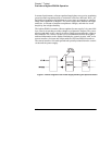
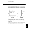
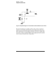
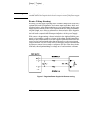
Multiple Loads
When connecting multiple loads to the power supply, each load should be
connected to the output terminals using separate connecting wires. This
minimizes mutual coupling effects between loads and takes full advantage of
the low output impedance of the power supply. Each pair of wires should be
as short as possible and twisted or shielded to reduce lead inductance and
noise pick-up. If a shield is used, connect one end to the power supply ground
terminal and leave the other end disconnected.
If cabling considerations require the use of distribution terminals that are
located remotely from the power supply, connect output terminals to the
distribution terminals by a pair of twisted or shielded wires. Connect each load
to the distribution terminals separately.
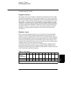
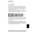
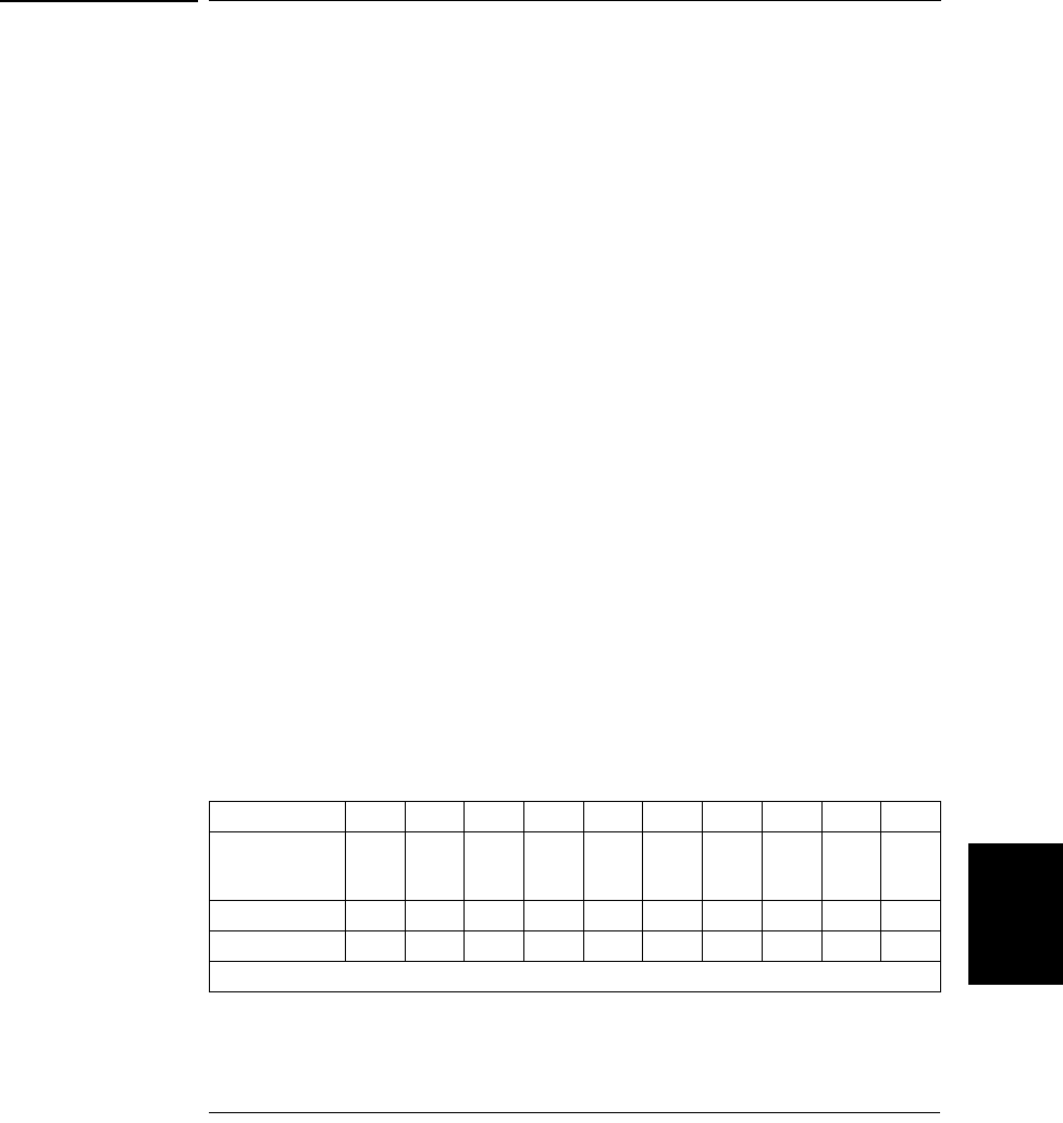
Table 7-1
. Wire Rating
AWG 10 12 14 16 18 20 22 24 26 28
Suggested
maximum
Current(amps)*
40 25 20 13 10 7 5 3.5 2.5 1.7
mW/ft 1.00 1.59 2.53 4.02 6.39 10.2 16.1 25.7 40.8 64.9
mW/m 3.3 5.2 8.3 13.2 21.0 33.5 52.8 84.3 133.9 212.9
*Single conductor in gree air at 30 °C with insulation