


#()!!)$#
'+#)P*""#(
'"$)$#)'$!
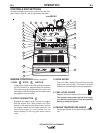
The AIR VANTAGE® 500 CUMMINS is equipped with
a 6-pin and a 14-pin connector. The 6-pin connector is
for connecting the K857 or K857-1 Remote Control or
for TIG welding, the K870 foot Amptrol or the K963-3
hand Amptrol. When in the CC-STICK or CV-WIRE
modes and when a remote control is connected to the
6-pin Connector, the auto-sensing circuit automatically
switches the OUTPUT control from control at the
welder to remote control.
When in the DOWNHILL PIPE mode and when a
remote control is connected to the 6-Pin or 14-Pin
connector, the output control is used to set the maxi-
mum current range of the remote.
-"%!When the OUTPUT CONTROL on the
welder is set to 200 amps the current range on the
remote control will be 40-200 amps, rather than the
full 40-300 amps. Any current range that is less than
the full range provides finer current resolution for more
fine tuning of the output.
The 14-pin connector is used to directly connect a
wire feeder control cable. In the CV-WIRE mode,
when the control cable is connected to the 14-pin con-
nector, the auto-sensing circuit automatically makes
the Output Control inactive and the wire feeder volt-
age control active.
#$),85>1G9B565545BG9D812E9<D9>G5<49>7
F?<D1753?>DB?<9C3?>>53D54D?D85@9>3?>>53
D?B4?>?D3?>>53D1>ID89>7D?D85@9>3?>>53
D?B
------------------------------------------------------------------------
*-!'.%$,''%)!(
Start the engine and set the “IDLER” control switch to
the “High Idle” mode. Voltage is now correct at the
receptacles for auxiliary power. This must be done
before a tripped GFCI receptacle can be reset proper-
ly. See the MAINTENANCE section for detailed infor-
mation on testing and resetting the GFCI receptacle.
The auxiliary power capacity of the AIR VANTAGE®
500 CUMMINS is 12,000 watts of 60 Hz, single phase
or 20,000 watts of 60Hz, three phase power. The
auxiliary power capacity rating in watts is equivalent to
volt-amperes at unity power factor. The maximum per-
missible current of the 240 VAC output is 50 A. The
240 VAC single phase output can be split to provide
two separate 120 VAC outputs with a maximum per-
missible current of 50 A per output to two separate
120 VAC branch circuits. The output voltage is within
± 10% at all loads up to rated capacity.
The AIR VANTAGE® 500 CUMMINS has two 20
Amp-120VAC single phase(5-20R) GFCI duplex
receptacles, one 50 Amp-120/240 single phase VAC
(14-50R) receptacle and one 240VAC three phase
(15-50R) receptacle. The auxiliary power receptacles
should only be used with three wire grounded type
plugs or approved double insulated tools with two wire
plugs. The current rating of any plug used with the
system must be at least equal to the current capacity
of the associated receptacle.
A 240VAC 3 phase plug is provided loose with the
machine.
#$) The two 120V GFCI receptacles and the two
120 volt circuits of the 120/240V receptacle are con-
nected to different phases and can not be paralleled.
()#.%$,'$##)$#(
The AIR VANTAGE® 500 CUMMINS is suitable for
temporary, standby or emergency power using the
engine manufacturer’s recommended maintenance
schedule.
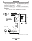
The AIR VANTAGE® 500 CUMMINS can be perma-
nently installed as a standby power unit for 240 volt-3
wire, 50 amp service. Connections must be made by a
licensed electrician who can determine how the
120/240 VAC power can be adapted to the particular
installation and comply with all applicable electrical
codes. The following information can be used as a
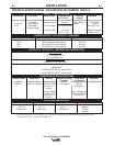
guide by the electrician for most applications. Refer to
the connection diagram shown in Figure A.1.
1. Install the double-pole, double-throw switch
between the power company meter and the premis-
es disconnect.
Switch rating must be the same or greater than the
customer’s premises disconnect and service over cur-
rent protection.
,'##