


)'$*!($$)#
'+#)P*""#(
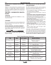
Observe all Safety Guidelines detailed throughout this manual
If for any reason you do not understand the test procedures or are unable to perform the tests/repairs safely, contact your
!?31<!9>3?<>ED8?B9J5495<4(5BF935139<9DI for technical troubleshooting assistance before you proceed.
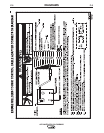
*)$#
%'$!"(
(."%)$"(
%$((!
*(
'$""#
$*'($)$#
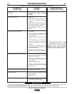
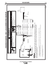
Engine goes to low idle but does not
stay at low idle.
No welding output or auxiliary output.
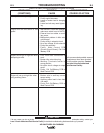
Welder has some/ no output and no
control. Auxiliary output OK
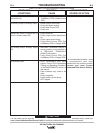
No welding output. Auxiliary output
OK.
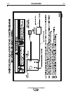
No auxiliary power.
1. Faulty Peripheral PCB, Pull
Coil/Battery PCB or Weld Control
PCB.
1. Broken lead in rotor circuit.
2. Faulty field diode module.
3. Faulty Weld Control PCB.
4. Faulty rotor.
1. Faulty remote kit.
2. Faulty output control potentiome-
ter.
3. Faulty output control wiring.
4. Faulty Weld Control PCB, Pull
Coil/Battery PCB or Chopper PCB.
1. WELDING TERMINALS switch in
wrong position, be sure switch is
in WELDING TERMINALS
ALWAYS ON position.
2. Faulty Weld Control PCB, Pull
Coil/Battery PCB or Chopper PCB.
1. GFCI Receptacle may have
tripped. Follow “GFCI Receptacle
Testing and Resetting Procedure”
in the MAINTENANCE section of
this manual.
2. Open breakers may need to be
reset.
3. Faulty receptacle.
4. Faulty auxiliary circuit wiring.
5. GFCI tripped.
I
f all recommended possible areas
of misadjustment have been
checked and the problem persists,
?>D13D I?EB <?31< !9>3?<>
ED8?B9J5495<4(5BF935139<9DI