


$%')$#
)!$*)%*)")'(
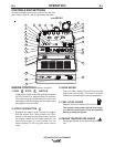
The digital meters allow the output voltage (CV-WIRE
mode) or current (CC-STICK, DOWNHILL PIPE and
TIG modes) to be set prior to welding using the OUT-
PUT control knob. During welding, the meters display
the actual output voltage (VOLTS) and current
(AMPS). A memory feature holds the display of both
meters on the seven seconds after welding is
stopped. This allows the operator to read the actual
current and voltage just prior to when welding was
ceased. While the display is being held the left-most
decimal point in each display will be flashing. The
accuracy of the meters is ± 3%.
,!V"$V(!)$'V(,)
(Provides four selectable welding modes)
CV-WIRE
DOWNHILL PIPE
CC-STICK
TOUCH START TIG
'V$#)'$!
The ARC CONTROL WIRE/STICK knob is active in
the WIRE and STICK modes, and has different func-
tions in these modes. This control is not active in the
TIG mode.
CC-STICK mode: In this mode, the ARC CONTROL
knob sets the short circuit current (arc-force) during
stick welding. Increasing the number from -10(Soft)
to +10(Crisp) increases the short circuit current and
prevents sticking of the electrode to the plate while
welding. This can also increase spatter. It is recom-
mended that the ARC CONTROL be set to the mini-
mum number without electrode sticking. Start with a
setting at 0.
DOWNHILL PIPE mode: In this mode, the ARC
CONTROL knob sets the short circuit current (arc-
force) during stick welding to adjust for a soft or a
more forceful digging arc (Crisp). Increasing the num-
ber from -10(Soft) to +10(Crisp) increases the short
circuit current which results in a more forceful digging
arc. Typically a forceful digging arc is preferred for
root and hot passes. A softer arc is preferred for fill
and cap passes where weld puddle control and depo-
sition (“stacking” of iron) are key to fast travel
speeds. It is recommended that the ARC CONTROL
be set initially at 0.
CV-WIRE mode: In this mode, turning the ARC CON-
TROL knob from -10(soft) to +10(crisp) changes the
arc from soft and washed-in to crisp and narrow. It
acts as an inductance/pinch control. The proper set-
ting depends on the procedure and operator prefer-
ence. Start with a setting of 0.
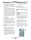
'+#)P*""#(
,!#)'"#!((,)
In the WELD TERMINALS ON position, the output
is electrically hot all the time. In the REMOTELY
CONTROLLED position, the output is controlled by
a wire feeder or amptrol device, and is electrically
off until a remote switch is depressed.
,'V'V+$!)")'V(,)
Matches the polarity of the wire feeder voltmeter to
the polarity of the electrode.
%#$##)$'
For attaching optional remote control equipment.
Includes auto-sensing remote control circuit.
%#$##)$'
For attaching wire feeder control cables. Includes
contactor closure circuit, auto-sensing remote con-
trol circuit, and 120VAC and 42VAC power.
#$) When a wire feeder with a built in welding
voltage control is connected to the 14-pin connec-
tor, do not connect anything to the 6-pin connec-
tor.
,!$*)%*))'"#!(#
These 1/2” - 13 studs with flange nuts provide
welding connection points for the electrode and
work cables. For positive polarity welding the elec-
trode cable connects to the “+” terminal and the
work cable connects to this “-” terminal. For nega-
tive polarity welding the work cable connects to the
“+” terminal and the electrode cable connects to
this “-” terminal.
*-!'.%$,'$#)'$!(
(Items 19-23)
+(#!%('%)!
This is a 120/240VAC (14-50R) receptacle that
provides 240VAC or can be split for 120VAC single
phase auxiliary power. This receptacle has a 50
amp rating. Refer to the AUXILIARY POWER
RECEPTACLES section in the installation chapter
for further information about this receptacle. Also
refer to the AUXILIARY POWER OPERATION
section later in this chapter.