


$%')$#
$!%'((*'*
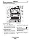
The gauge displays the engine oil pressure when
the engine is running.
##V%'$))$#
The yellow engine protection light remains off
with proper oil pressure and under normal oper-
ating temperatures. If the light turns on, the
engine protection system will stop the engine.
Check for proper oil level and add oil if neces-
sary. Check for loose or disconnected leads at
the oil pressure sender located on the engine.
The light will remain on when the engine has
been shut down due to low oil pressure or over-
temperature condition.
))'.'#!)
The yellow engine alternator light is off when bat-
tery charging system is functioning normally. If
light turns on the alternator or the voltage regula-
tor may not be operating correctly. The light will
remain on when the engine is stopped and the
run/stop switch is in the run position.
!'(,)
Has two positions as follows:
A) In the “High” position , the engine runs at
the high idle speed controlled by the governor.
B) In the “Auto” / position, the
idler operates as follows:
a. When switched from “High” to “Auto” or after
starting the engine, the engine will operate at
full speed for approximately 12 seconds and
then go to low idle speed.
b. When the electrode touches the work or power
is drawn for lights or tools (approximately 100
Watts minimum) the engine accelerates and
operates at full speed.
c. When welding ceases and the AC power load
is turned off, a fixed time delay of approximate-
ly 12 seconds starts.
d. If the welding or AC power load is not restart-
ed before the end of the time delay, the idler
reduces the engine speed to low idle speed.
e. The engine will automatically return to high
idle speed when the welding load or AC power
load is reapplied.
4<5B$@5B1D9?>1<5H35@D9?>C
When the WELDING TERMINALS switch is in
the “Remotely Controlled” position the idler will
operate as follows:
a. When the triggering device (Amptrol, Arc Start
Switch, etc.) is pressed the engine will acceler-
ate and operate at full speed provided a weld-
ing load is applied within approximately 12
seconds.
• If the triggering device remains pressed but no
welding load is applied within approximately 12
seconds the engine may return to low idle
speed.
• If the triggering device is released or welding
ceases the engine will return to low idle speed
after approximately 12 seconds.
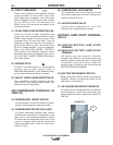
,!#$#)'$!(D5=C
D8B?E78
$*)%*)$#)'$!
The OUTPUT dial is used to preset the output
voltage or current as displayed on the digital
meters for the four welding modes. When in the
CC-STICK, DOWNHILL PIPE or CV-WIRE
modes and when a remote control is connected
to the 6-Pin or 14-Pin Connector, the auto-sens-
ing circuit automatically switches the OUTPUT
CONTROL from control at the welder to the
remote control.
In the CV-WIRE mode, when the wire feeder
control cable is connected to the 14-Pin
Connector, the auto-sensing circuit automatically
makes OUTPUT CONTROL inactive and the
wire feeder voltage control active.
When in the DOWNHILL PIPE mode and when
a remote control is connected to the 6-Pin or 14-
Pin connector, the output control is used to set
the maximum current range of the remote.
-"%!When the OUTPUT CONTROL on
the welder is set to 200 amps the current range
on the remote control will be 40-200 amps,
rather than the full 40-300 amps. Any current
range that is less than the full range provides
finer current resolution for more fine tuning of
the output.
When in the TOUCH START TIG mode and
when a Amptrol is connected to the 6-Pin
Connector, the OUTPUT dial is used to set the
maximum current range of the CURRENT CON-
TROL of the Amptrol.
'+#)P*""#(