


#()!!)$#
'+#)P*""#(
$##)$#$ !#$!#!
)',''(
(8ED?66G5<45B256?B5=1;9>71>I5<53DB931<3?>
>53D9?>C
------------------------------------------------------------------------
?>>53D9?>?6!#!#$'!# D?D85'
+#)P*""#(
(8EDD85G5<45B?66
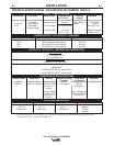
2. Connect the LN-7, LN-8 OR LN-742 per instruc-
tions on the appropriate connection diagram in
Section F.
3. Set the "WIRE FEEDER VOLTMETER" switch to
either "+" or "-" as required by the electrode being
used.
4. Set the "MODE" switch to the "CV WIRE " posi-
tion.
5. Set the "ARC CONTROL" knob to "0" initially and
adjust to suit.
6. Set the "WELD TERMINALS" switch to the
"REMOTELY CONTROLLED" position.
7. Set the "IDLE" switch to the "HIGH" position.
?>>53D9?>?6!#D?D85'+#)P
*""#(
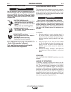
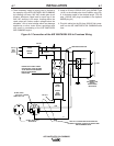
These connections instructions apply to both the LN-
15 Across-The-Arc and Control Cable models. The
LN-15 has an internal contactor and the electrode is
not energized until the gun trigger is closed. When the
gun trigger is closed the wire will begin to feed and the
welding process is started.
(8EDD85G5<45B?66
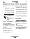
For electrode Positive, connect the electrode
cable to the "+" terminal of the welder and work
cable to the "-" terminal of the welder. For elec-
trode Negative, connect the electrode cable to the
"-" terminal of the welder and work cable to the "+"
terminal of the welder.
3B?CC)85B3"?45<
• Attach the single lead from the front of the LN-15
to work using the spring clip at the end of the
lead. This is a control lead to supply current to
the wire feeder motor; it does not carry welding
current.
• Set the "WELD TERMINALS" switch to "WELD
TERMINALS ON".
• When the gun trigger is closed, the current sens-
ing circuit will cause the AIR VANTAGE® 500
CUMMINS engine to go to the high idle speed,
the wire will begin to feed and the welding
process started. When welding is stopped, the
engine will revert to low idle speed after approxi-
mately 12 seconds unless welding is resumed.
?>DB?<12<5"?45<
• Connect Control Cable between Engine Welder
and Feeder.
• Set the "WELD TERMINALS" switch to
"REMOTELY CONTROLLED"
• Set the MODE switch to the "CV-WIRE " position.
• Set the "WIRE FEEDER VOLTMETER" switch to
either "+" or "-" as required by the electrode polar-
ity being used.
• Set the "ARC CONTROL" knob to "0" initially and
adjust to suit.
• Set the "IDLE" switch to the "AUTO" position.
• When the gun trigger is closed, the current sens-
ing circuit will cause the AIR VANTAGE® 500
CUMMINS engine to go to the high idle speed,
the wire will begin to feed and the welding
process started. When welding is stopped, the
engine will revert to low idle speed after approxi-
mately 12 seconds unless welding is resumed.
,'##