


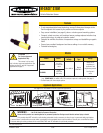

M-GAGE
®
S18M — Vehicle Detection Sensor
4 P/N 114430 rev. A
Banner Engineering Corp. • Minneapolis, MN U.S.A.
www.bannerengineering.com • Tel: 763.544.3164
P/N 114430 rev. A 5
M-GAGE
®
S18M — Vehicle Detection Sensor
Banner Engineering Corp. • Minneapolis, MN U.S.A.
www.bannerengineering.com • Tel: 763.544.3164
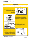
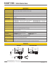
SMP1 Flex
Conduit Plug
" Flex
Conduit
2" PVC
Conduit
6" Below
Grade
Figure 2. Below-grade installation
3.
1.
2.
Below-Grade Installation
Materials
• M-GAGE S18M Sensor
• SMP1 Conduit Plug
• 2" Schedule 80 rigid PVC conduit (1.5" may be used if there
is only one 90° bend); total length and number of elbows
depend on installation layout
• 2" (or 1.5") rigid PVC end cap (1 per installation)
• " I.D. flexible, liquid-tight, non-metallic conduit (same
length as PVC conduit used for application)
• DPB1 Portable Programming Box
Procedure
1) Lay out 2" (or 1.5") PVC in the desired configuration. For
the best sensor performance, the sensing location (located
at the end of the conduit run) should be 6" below the final
surface. Provide an access point where the PVC comes
above grade (where the sensor and flex conduit can be fed
in or pulled out, as required).
2) Secure the end cap to the PVC, at the sensing location.
3) Measure the overall length of the PVC run, from the
sensing location to the control panel.
4) Cut a section of " flex conduit to span the total distance
from the control panel to the sensing location.
5) Thread the sensor into the SMP1 conduit plug. Feed the
sensor cable into the flex conduit, until the sensor and plug
are snugly seated in the end of the flex conduit.
6) Feed the flex conduit by hand, sensor-end first, into the
PVC access point until the sensor reaches the PVC end cap.
7) Secure the remaining flex conduit from the access point to
the control cabinet.
8) After the sensor is configured (see following sections), wire
the sensor into the control device and power supply per the
wiring diagram on page 8.
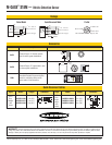
Above-Grade Installation
Materials
• M-GAGE S18M Sensor
• SMP2 Conduit Plug
• " Schedule 40 PVC electrical conduit; total length and
number of elbows depend on installation layout
• Electrician’s fishtape
• Silicone adhesive
• DPB1 Portable Programming Box
Procedure
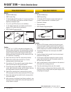
1) Mount the PVC electrical conduit from the sensing point
to the control panel. Plastic conduit should be used for at
least the first 6.1 m (20') from the sensing point; metal or
flexible conduit may be used the remainder of the distance.
2) Thread the S18M sensor into the threads of the SMP2
conduit plug.
3) Feed the fishtape into the conduit, from the control panel
towards the sensing point.
4) Pull the sensor cable back through the conduit, until the
sensor almost reaches the end of the plastic conduit. Do
NOT pull sensor into conduit.
5) Apply a small amount of silicone adhesive to the outside of
the conduit at the sensing point end.
6) Press the conduit plug into the end of the conduit.
7) After the sensor is configured (see following section), wire
the sensor into the control device and power supply per the
wiring diagram on page 8.
Figure 3. Above-grade installation
SMP2 Conduit Plug
" PVC Conduit
2.
1.