


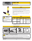
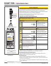

M-GAGE
®
S18M — Vehicle Detection Sensor
4 P/N 114430 rev. A
Banner Engineering Corp. • Minneapolis, MN U.S.A.
www.bannerengineering.com • Tel: 763.544.3164
P/N 114430 rev. A 5
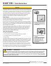
M-GAGE
®
S18M — Vehicle Detection Sensor
Banner Engineering Corp. • Minneapolis, MN U.S.A.
www.bannerengineering.com • Tel: 763.544.3164
Sensor Configuration
For most applications, configure the M-GAGE sensor remotely, via the DPB1 Portable
Programming Box, which provides programming access to an underground or
otherwise inaccessible sensor. For optimum performance, the sensor must be fixtured
so that it will not move either during or following configuration.
Configuration using the sensor’s built-in push button is useful primarily for
demonstration and troubleshooting purposes.
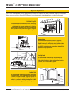
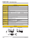
Conguration via the DPB1 Portable Programming Box
PC
IR
Figure 4. Using the model DPB1 portable
programming box
“Single-Click” to Set Background
Condition
“Double-Click” to Set Sensitivity
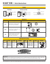
Brown Blue Gray White or Black
Power ON LED
Configuration/
Output ON LED
Push Button
Set Background Condition (No Vehicle Present)
Wire the M-GAGE sensor to the DPB1 as shown in Figure 4. Remove all vehicles and all other
metal objects temporarily in the sensing area, before setting the background condition.
Configuration Result
Set
Background
• “Click” the DPB1 TEACH push button once. • Sensor learns background.
• Output indicator LED flashes
approximately 12 times, while
background is taught.
• Sensor returns to RUN mode.
Set Sensitivity Level (6 sensitivity levels; level 1 least sensitive, level 6 most sensitive)
Configuration Result
Sensitivity
Mode
• “Double-click” the DPB1 TEACH push button. • Output LED flashes every 2 seconds;
sensor is at sensitivity level 1.
(When using the DPB1, the sensor
always reverts to sensitivity level 1.)
Adjust Sensitivity
• To increase the sensitivity in increments,
“click” the push button again;
continue until desired
sensitivity level is reached.
• Output LED will flash from 1 to 6
times every 2 seconds to indicate
sensor’s sensitivity level (e.g., twice
to indicate level 2).
• “Double-click” push button
to save setting.
• Sensor returns to RUN mode
Test
Operation
• Drive a vehicle past/over sensor to trip the
output; verify Output LED comes ON as
expected. Use a small/light vehicle to ensure
larger vehicles will be detected later.
• Adjust the sensitivity as needed.
Prepare for
Operation
• Disconnect DPB1 and hardwire sensor to
permanent power supply/output device (user-
supplied). See page 8.
Conguration via the Sensor Push Button
(For demonstration and troubleshooting only.)
Follow the instructions in the table above, with the following exceptions.
Set Background Condition (No Vehicle Present):
• Press and hold the push button for 2 seconds, until the Output LED turns red.
• Release, and then “click” the push button once.
Set Sensitivity Level:
• Press and hold the push button for 2 seconds, until the Output LED turns red.
• Release, and then quickly “double-click” the push button. Increase the sensitivity by
increments as described above.
• When the sensor is set to desired sensitivity level, double-click push button to return
sensor to RUN mode.