


75.5079.08 20061129 Page 4 of 13
ELECTRICAL
INSTALLATION
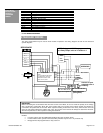
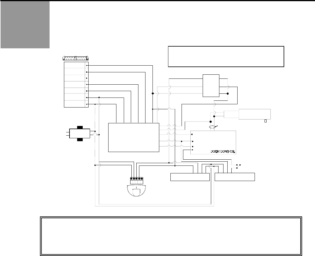
Option 3 – Double
Pole Double Throw
Switch
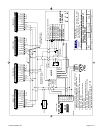
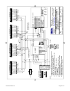
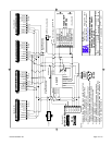
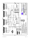
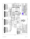
The wiring diagram below shows how to wire a DPDT switch to control the On-Off-Hold function, as well as data
between the motor and the LO21P.
brown
red/white
white
gray
purple
orange
LO-21P
24 V
TRANSFORMER
DATA + 7
DATA - 6
N.C. 5
N.O. 4
COM 3
POWER 2
POWER 1
M
O
T
O
R
+
red
black
blue
green
115 VAC
BODYGUARD
1 2 3 4 5
EAGLE
OPERATOR
-
MOTOR VOLTAGE
COMMON
ACTIVATION
STALL
8 7 6 5 4 3 2 1
Contacts to open
at desired point of
inhibiting
Approach SuperScan
Stall SuperScan
(Swing Side)
AUTO
OFF
HOLD
Door Control
1 2 3 4 5 6 7 8
blk/white
D
O
U
B
L
E
-
P
O
L
E
D
O
U
B
L
E
T
H
R
O
W
S
W
I
T
C
H
SAFETY
yellow
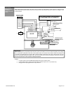
IMPORTANT:
Before connecting the red and black wires from the LO-21P to the Motor, be sure to check the polarity of the voltage
with a multi-meter, to determine which wire is the positive side. The red wire of the lockout module must always be
connected to the positive side of the motor. When a positive reading is observed on the meter, (while the door is in hold
open) the red probe indicates the positive side. Thus, the red wire of the lockout will always be attached to whatever
wire the red probe was on when a positive reading was obtained.
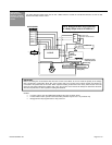
NOTES:
• For pairs of doors, wire the additional SuperScans the same as shown above.
• For the inhibit function, operator mounted auxiliary switches may be used – dry contacts only.
• Bodyguard must be programmed to a relay value of 2.
NOTE: Bodyguard MUST be programmed
to a Relay Output value of 2. Default is 1.