


75.5079.08 20061129 Page 5 of 13
SET-UP
INSTRUCTIONS
Upon completion of all wiring, proceed with the set-up as follows:
1. Insure that the On-Off-Hold Open switch is in the ON position, and insure that the door control is powered and
operating normally.
2. Power the Bodyguard sensor and, using a BEA Remote Control, unlock the sensor and change the
Output Configuration to a value of 2. If necessary, refer to the Bodyguard User’s Guide for programming
instruction.
3. Power the LO-21P on with 12-24 VAC/VDC, and insure all sensors or other devices in the application are
properly powered
4. Observe the green LED on the Bodyguard upon powering. With the door in the closed position, the green LED
should begin blinking, then expire approximately 5 seconds thereafter to indicate a successful set-up for the
closed-door position.
5. Activate the door to the open position, the Bodyguard should once again begin flashing green, then expire
approximately 5 seconds thereafter to indicate a successful set-up for the open-door position. If the door goes
into safety swing as soon as it starts to close and you have a time delay set for the length of the closing cycle,
reverse the black and red wires to the motor input for DC units. Correct any faults before proceeding.
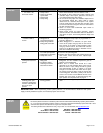
To perform a quick test by remote control to check motor wire polarity, perform the
following:
• Place On-Off-Hold switch in the ON or AUTO position.
• Activate the door and immediately walk into the Bodyguard detection pattern while
door is open. Door should be holding open at this point. Make sure there is no Eagle
activation during this time.
• Unlock the Bodyguard and press Magic Wand + 2. Green LED will begin flashing – If
door closes while flashing green, check for correct polarity at the red and black wire
from lockout.
6. Once the Bodyguard has learned the open and closed door positions, observe the green and red LED’s on the
LO-21P. Walk in and out of the field of detection for the Bodyguard while the door is open, and then again when
it is closed. The LED’s indicate the following:
GREEN LED: The green LED, when illuminated, indicates that there is detection at the
Bodyguard while the door is in the open position.
If someone steps into the Bodyguard detection zone when the door is open, the LO-21P’s
Green LED will illuminate to indicate that the Bodyguard will be connected to the activation
circuitry of the door, thus holding the door open as long as there is detection.
Green LED will also illuminate when the activating device (Eagle) is triggered, or when On-Off-
Hold Open switch is placed to the Hold Open position.
RED LED: The red LED, when illuminated, indicates that there is detection at the Bodyguard
while the door is in the closed position. It may also indicate that there is an activation signal
from the Eagle or the Hold Open switch.
When the door is closed, and someone steps into the detection zone of the Bodyguard, the red
LED on the LO-21P will illuminate, indicating that it will ignore any activation signal it receives.
Therefore, the door will remain closed until the Bodyguard detection zone is clear. Once the
Bodyguard zone is clear and the door has been activated it will open and remain open for the
hold time set by the motion sensor and/or door control, and will also hold open during detection
at Bodyguard.
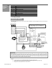
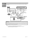
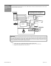
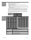
CLOSED DOOR OPEN DOOR CLOSING DOOR
0 Volts DC 9 to 12 Volts DC 8 Volts DC
If the Bodyguard learns a “door closed” position, but does not execute a set-up for the
“open door position”, place the door to a hold open position. With a BEA remote control,
unlock the Bodyguard, and with the door in the open position, press the Magic Wand key
and then the number 2 – the Bodyguard should begin flashing green to signify a set-up. If
it does not, this will be a quick indication that the improper data is being sent for the
“open door” position. Check to insure that data exists on the data lines leading into the
Bodyguard. In the full open position, voltage should be approximately 9 to 12 volts DC. If
it is not, check the data lines (White wire on terminal 6 and Red/White wire on terminal 7)
for correct voltage (see chart).
STOP
2
+