


75.5079.08 20061129 Page 7 of 13
COMPANY
CONTACT
TROUBLE-
SHOOTING
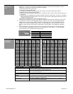
PROBLEM PROBABLE CAUSE CORRECTIVE ACTION
Door will not open
– all LED’s are
OFF at the LO21P
1. Faulty door control
2. Faulty LO21P
3. Faulty On-Off-Hold
Open switch
4. Faulty Eagle
5. Faulty wiring
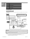
1. Insure input power is good at LO21P – orange and
brown wires. Should be 12 to 24 volts AC or DC.
2. Go directly to door control and jumper common and
activation input. If door opens, proceed to next step. If
not, replace/repair faulty door control.
3. Go to LO21P and jumper the red/white striped wire to
the black/white striped wire. Green LED on LO21P
should come on, and door should open. If not, replace
LO21P. If LED comes on, but door does not open, check
to insure that the blue and green wires are connected to
the door control properly.
4. Check to insure that On-Off-Hold Open switch is
functioning properly.
5. Check Eagle sensor for proper operation. Jumper
common and N.O. terminals while wires are attached. If
door does not open, check wiring between Eagle and
LO21P.
Door will not open
– red LED is ON at
LO21P
1. Bodyguard is in detection
2. Bodyguard not
programmed properly
3. Faulty wiring between
Bodyguard and LO21P
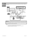
1. Launch a setup on Bodyguard
2. Insure Bodyguard relay output is programmed to a
value of 2. Default is 1.
3. When Bodyguard is in detection, an open circuit
occurs at the purple and gray wires on the LO21P.
Thus if there is any break in wiring between purple
and gray and the LO21P, the lockout will react the
same as if the Bodyguard were in detection. Insure
there are no breaks in the wiring.
Door will not close 1. On-Off-Hold Open switch
is in Hold Open position
2. Bodyguard is in detection
3. Faulty door control
1. Place switch in On or Auto position
2. Launch a setup at Bodyguard
3. Remove wire from common and activate terminal at
door control, if door does not close, replace/repair
faulty control.
Bodyguard keeps re-
learning with each door
position
1. Incorrect data polarity at
Bodyguard
2. Insufficient voltage
switching at red and
black wire of LO21P
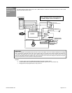
1. Insure that the white wire goes to terminal 6 of the
Bodyguard, and the red/white striped wire goes to
terminal 7 of the Bodyguard
2. When door is closed, there should be 0 volts
observed on the red and black wires of the LO21P.
When the door is open, voltage should be greater
than approximately 9 volts. If voltage is not great
enough at red and black wires when door is open,
the LO21P will not be able to send the correct data
to the Bodyguard. Remember, polarity must also be
correct. The red wire must ALWAYS connect to the
positive wire of the motor, as observed during door
open position. See important note on page 2.
As the door is closing,
the Bodyguard, upon
seeing the closing door,
seems to reactivate the
door to the open
position
1. Dipswitch 6 at LO21P is
in wrong position
1. Place dipswitch 6 in opposite position and re-test the
door
IMPORTANT NOTE: When experiencing sensor system problems, it is recommended to disable the main power
supply as to fully disable the system, until necessary repairs can be made.
Do not leave problems unresolved. If a satisfactory solution cannot be achieved after troubleshooting a problem, please call B.E.A.,
Inc. If you must wait for the following workday to call B.E.A., leave the door inoperable until satisfactory repairs can be made. Never
sacrifice the safe operation of the automatic door or gate for an incomplete solution.
The following numbers can be called 24 hours a day, 7 days a week. For more information, visit www.beasensors.com.
West: 1-888-419-2564 Mid-West: 1-888-308-8843
South-East: 1-800-407-4545 North-East: 1-866-836-1863
US and Canada: 1-866-249-7937 Canada: 1-866-836-1863