


75.5079.08 20061129 Page 6 of 13
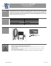
SETUP
INSTRUCTION
Cont.
DIPSWITCH
6, 7 and 8
OPERATION
7. Adjustment is necessary to configure the dipswitches to obtain the correct lock out time delay. To set the
dipswitches( 1 through 5) for lock out time, perform the following:
Activate the door to the open position.
Time the overall door closing cycle
Configure the dip switches according to the chart on Page 4 for the lockout time that is required
Activate the door again to the open position
Stand outside of the Bodyguard detection pattern, and while the door is closing, observe the red LED on the
Bodyguard
The red LED on the Bodyguard should NOT illuminate during the closing cycle. If it does, it is probably
seeing the door at the very last degree or two of door closing, which would indicate that the lock out time
needs to be slightly increased.
Reconfigure the dipswitches to add 1 second of lock out time.
When the lock out time is correct. The red LED will not illuminate during the entire closing cycle of the door.
8. The last test is to insure that the Bodyguard detects an object as soon as the door has stopped closing.
Simply allow the doors to begin closing, and step in behind the doors, into the Bodyguards field of
detection. The red LED shall illuminate and remain on at the Bodyguard, and at the LO-21P, as soon as
the door reaches the fully closed position, provided that an object remains in the Bodyguard’s detection
field.
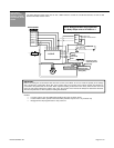
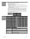
9. Set the dipswitches according to the chart below to achieve the desired lockout time. The total lockout time
is the sum total of the dipswitches that are in the ON position. For easy reference, use the timetables
below. Default time is 7 seconds (times are approximate).
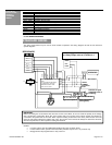
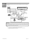
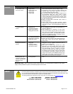
Dipswitch 6 Position Description of Performance
ON (Default) The LO21P expects to see voltage coming in at the red and black wire while the
door is in the Open position. Typical for DC motors.
OFF The LO21P expects to see voltage coming in at the red and black wire while the
door is in the Closed position.
Dipswitch 7 and 8
Position
Description of Performance
7 OFF / 8 ON (Default) The LO21P CLOSES the Safety circuit (yellow wire) upon a Bodyguard
Detection during the door closed position
7 ON / 8 OFF The LO21P OPENS the Safety circuit (yellow wire) upon a Bodyguard
Detection during the door closed position
Dipswitch # Time Delay (seconds)
1 1
2 2
3 4
4 8
5 16
Time
Delay
(sec)
dip 1
1 sec
dip 2
2 sec
dip 3
4 sec
dip 4
8 sec
dip 5
16 sec
Time
Delay
(sec)
dip 1
1 sec
dip 2
2 sec
dip 3
4 sec
dip 4
8 sec
dip 5
16 sec
1 on off off off off 17 on off off off on
2 off on off off off 18 off on off off on
3 on on off off off 19 on on off off on
4 off off on off off 20 off off on off on
5 on off on off off 21 on off on off on
6 off on on off off 22 off on on off on
7 on on on off off 23 on on on off on
8 off off off on off 24 off off off on on
9 on off off on off 25 on off off on on
10 off on off on off 26 off on off on on
11 on on off on off 27 on on off on on
12 off off on on off 28 off off on on on
13 on off on on off 29 on off on on on
14 off on on on off 30 off on on on on
15 on on on on off 31 on on on on on
16 off off off off on