


12
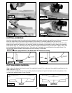
DISCONNECT MACHINE FROM POWER SOURCE.
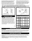
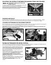
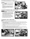
1. Loosen the bevel lock handle and move the cutting arm all the way to the right. Tighten the bevel lock handle.
2. Place one end of a square (A) Fig. 22 on the table and the other end against the blade. Check to see if the blade
is 90° to the table (Fig. 22).
3. If an adjustment is necessary, loosen the locknut (A) Fig. 23. Turn the screw (B) until the head of the screw
contacts the casting (C) when the blade is 90° to the table. Tighten the locknut (B).
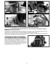
4. Loosen the bevel lock handle and move the cutting arm all the way to the left bevel position. Tighten the bevel
lock handle.
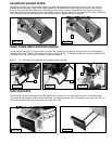
5. Use a combination square (A) Fig. 24 to see if the blade is at 45° to the table.
6. If an adjustment is necessary, loosen the locknut (A) Fig. 25. Turn the screw (B) until the screw (B) contacts the
casting (C) when the blade is 45 degrees to the table. Tighten the locknut.
7. Check to see that the bevel pointer (A) Fig. 26 is pointing to the 45° mark on the bevel scale. To adjust the bevel
pointer (A), loosen the screw (B) and adjust the pointer (A). Tighten the screw (B) securely.
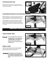
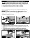
DISCONNECT MACHINE FROM POWER
SOURCE.
1. The downward travel of the saw blade should be
limited to prevent the saw blade from contacting
any metal surfaces of the machine. This adjustment
is made by loosening the locknut (A) Fig. 21, and
turning the adjusting screw (B) in or out.
2. Lower the blade as far as possible. Rotate the
blade by hand to ensure that the teeth do not
contact any metal surfaces. Adjust if necessary.
3. After the downward travel of the saw blade has
been adjusted, tighten the locknut (A).
ADJUSTING DOWNWARD TRAVEL OF SAW BLADE
Fig. 21
A
B
ADJUSTING 90° AND 45° BEVEL STOPS
A
Fig. 22
Fig. 23
C
B
A
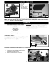
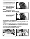
DISCONNECT MACHINE FROM POWER
SOURCE.
1. Lower the cutting arm. The saw blade (A) Fig. 20
should be parallel to the left edge (B) of the table
opening.
2. If an adjustment is necessary, loosen two screws
(C) Inset, and move the cutting arm until the blade
is parallel with the left edge (B) of the table
opening and centered in the slot. Then tighten the
two screws (C).
A
B
C
Fig. 20
ADJUSTING BLADE PARALLEL TO TABLE SLOT