


15
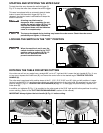
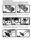
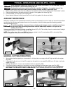
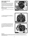
3. Use the 1/8" hex wrench to turn the vertical alignment set screw (Fig. E).
If you move the cutterhead from the raised to the lowered position and
the laser line moves horizontally away from the blade, turn the vertical
alignment set screw clockwise to correct. If the laser line moves
horizontally toward the blade, turn the vertical alignment set screw
counter-clockwise to correct. (Fig. F)
4. Reinstall the cover removed in STEP 2.
Fig. F
Fig. G
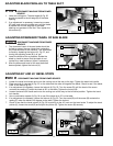
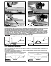
TO SET KERF ADJUSTMENT
1. Use the 1/8" hex wrench (A) Fig. H to turn the kerf adjustment screw that sets the laser line to either side of the
test cut (Fig. G). To adjust the line, turn the kerf adjustment screw counter-clockwise to move the line toward the
blade and clockwise to move the line away from the blade.
2. Remove the padlock. The laser miter saw is ready for normal use.
Fig. H
BRASS
HEX
NUT
VERTICAL
ALIGNMENT
SET SCREW
Fig. E
Never turn the brass hex nut in Fig. E.
A
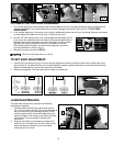
TO CHECK FOR VERTICAL ALIGNMENT
1. The vertical alignment is set correctly when the line does not move horizontally (sideways) as the cutting head is
raised and lowered. If the vertical alignment is correct, disregard this section and move to “TO SET KERF
ADJUSTMENT”.
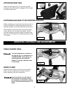
2. If the vertical alignment is not correct, turn the kerf adjustment screw one half turn, clockwise. Remove the screws
on both sides of the laser unit cover (Fig. A). Remove the cover.
SCREW
Fig. A
Fig. C
Fig. D
Fig. B
A
B
C
D
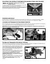
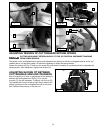
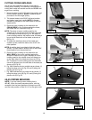
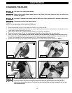
LASER MAINTENANCE
For best laser performance, perform the following
maintenance regularly:
1. Carefully clean sawdust from each laser lens (A)
Fig. I with a cotton swab (B). Do not use solvents of
any kind since they may damage the lens. Avoid
touching sharp points of the saw blade with your
hands or fingers. Dust build-up can block the laser
and prevent it from accurately indicating the
line-of-cut.
2. Remove the blade from the saw and clean pitch
build-up from the blade (Fig. J) Pitch build-up can
block the laser and prevent it from accurately
indicating the line-of-cut.
Fig. I Fig. J
A
B