


6 720 608 263
Installation instructions
11
3.6 Venting
3.6.1 Vent material and specifications
Establish vent clearances that comply with the vent
manufacturer's specifications. In all cases follow local
codes.
Note: Listed thimbles or collars are necessary to pass
through wall and ceiling partitions. If the vent system
passes through combustible areas where the vent
clearance requirements cannot be maintained, it is
permissible to chase straight sections of sealed 3 inch
single wall vent through 4 inch (or greater) Type-B vent.
The distance to combustibles using this chase
technique is 1 inch (check local codes).
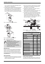
Vent lengths
The appliance should be located as close to the point
of termination as possible. The maximum vent length is
26 feet (8 m) with one 90 degree elbow. Subtract 2½
feet from the total vent length for each additional 90°
elbow used (a maximum of three 90° elbows are
permitted in the total vent length), or subtract 11/4
feet for every 45° elbow used. Horizontal sections of
vent must pitch upwards from heater ¼" for every foot
of horizontal length, to prevent the pooling of
condensate, and be supported at 4 foot intervals with
overhead hangers. See Table 2.
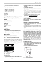
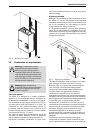
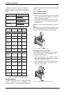
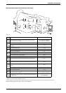
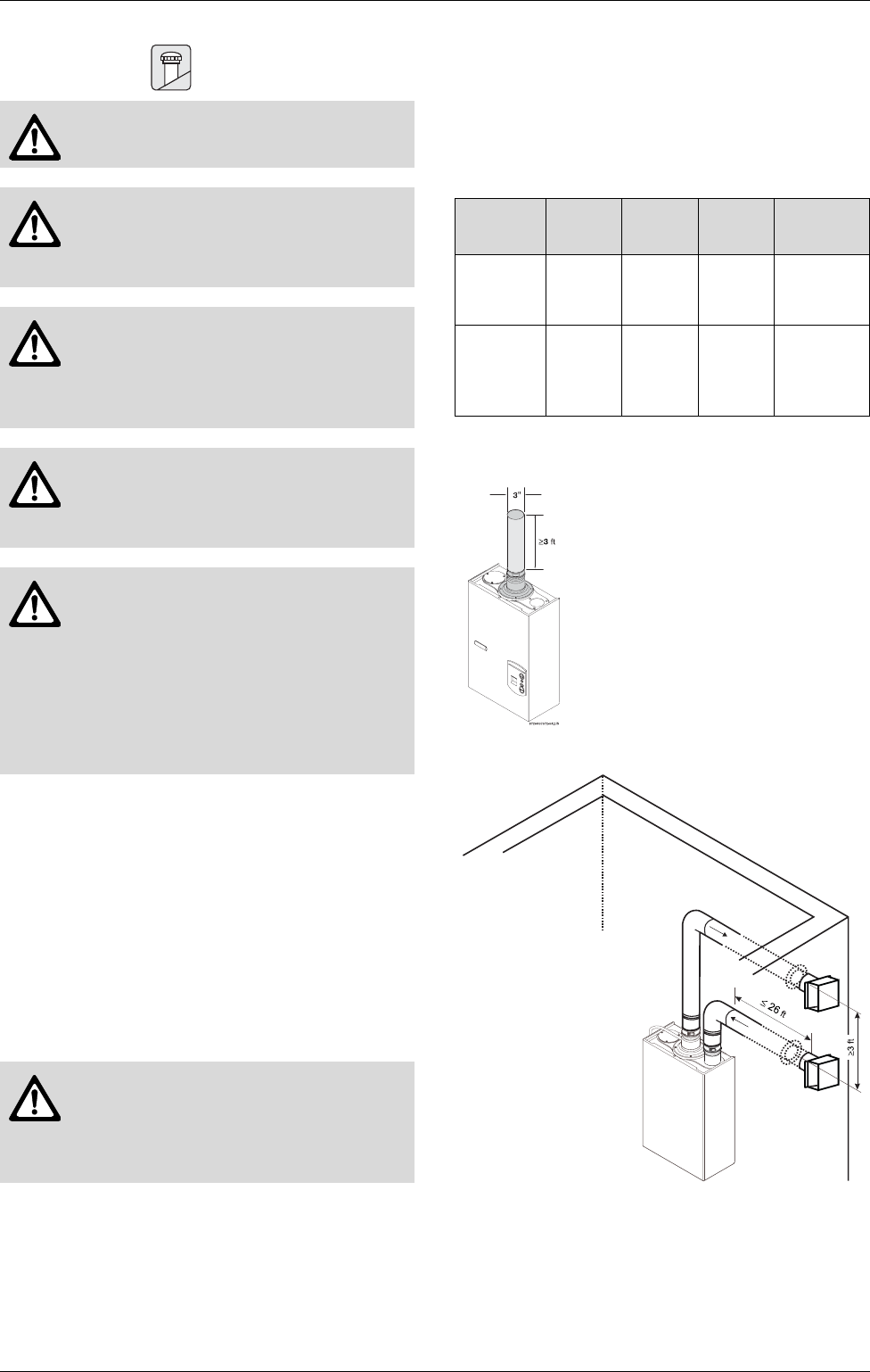
Minimum exhaust vent size and length
Fig. 8 Minimum exhaust vent length
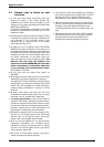
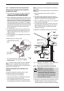
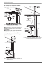
Fig. 9 Maximum vent and combustion air lengths
Vent material
The 2400 E requires 3 or 4 inch sealed single wall
stainless steel vent pipe (AL29-4C). Use of any other
vent material will void the manufactures warranty and
Danger: Do not combination vent this
appliance with any other appliance.
Warning: Do not reduce the vent
(exhaust and combustion) pipe sizes
and do not common vent with any other
vented appliance or stove.
Warning: Failure to vent the exhaust
gases to the outside with sealed
stainless steel vent pipe (AL29-4C)
may result in dangerous flue gases
filling the space in which it is installed.
Warning: Single wall exhaust pipe
MUST be chased through double wall
Type-B vent when passing through an
unconditioned space.
Warning: The vent system must be
installed by a qualified individual in
accordance with these instructions. If
improperly installed a hazardous
condition such as explosion or carbon
monoxide poisoning could result.
Bosch Water Heating will not be
responsible for improperly installed
appliances.
Warning: Type-B vent must never be
used as the actual exhaust vent system
for the appliance, because it is not gas
tight. This will create a serious health
hazard and void the warranty.
Diameter Minimum
length
Maximum
length
Material
Exhaust Vent
3 or 4
inches
3 feet
26 feet with
1 90°
elbow
Sealed single
wall stainless
steel (AL29-4C)
Intake Vent
3 or 4
inches
1 90° elbow
26 feet with
1 90°
elbow
Sealed
aluminum flex,
PVC or any
other rigid or
semi rigid pipe
Table 2 Venting specifications
The minimum exhaust vent length is
3 feet.
The use of a 90 degree elbow is
equivalent to 2 ½ ft in vent length.
The use of 45 degree elbow is
equivalent to 1 ¼ ft in vent length.
Reduce maximum
length 2 ½ ft for
each 90 elbow after
the first one and 1 ¼
ft for each 45 elbow.