


6 720 608 263
22
Installation instructions
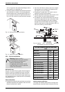
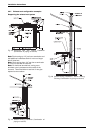
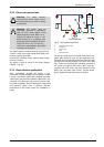
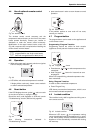
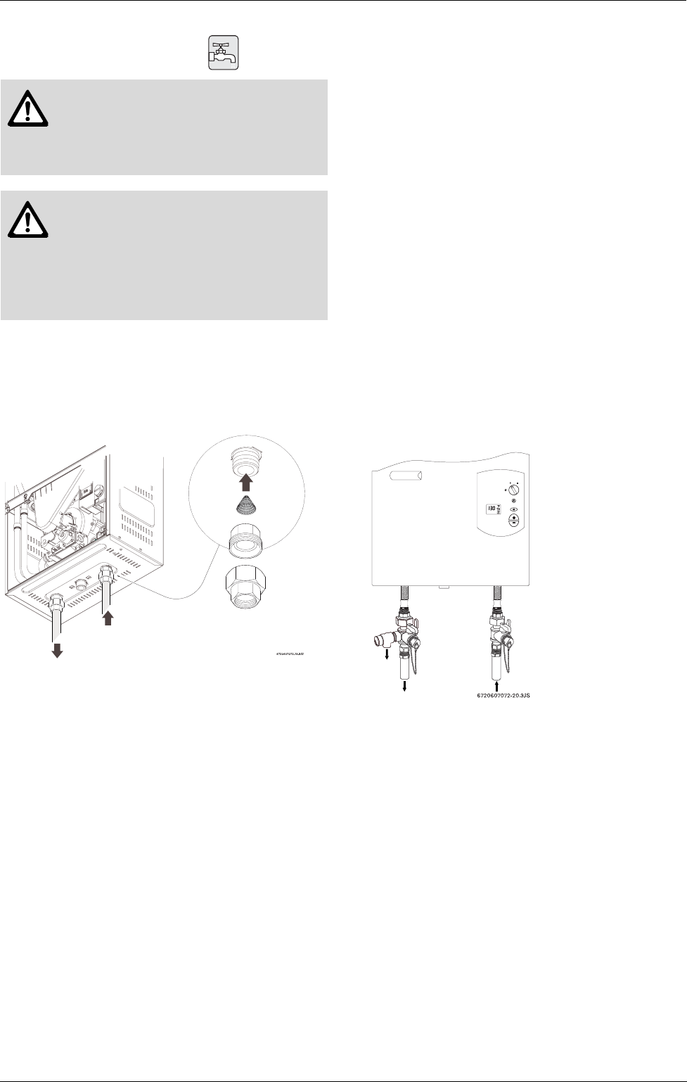
3.9 Water connections
B When facing the heater, the ¾” cold inlet connection
is on the bottom right and the hot connection is on
the bottom left. Centrally locating the water heater is
recommended to keep hot water distribution times
even throughout the structure.
Fig. 25
B The use of unions when connecting both water pipes
to the cold and hot water connections is required.
This will facilitate any necessary servicing.
B Plastic or PEX type plumbing line materials are not
suitable for connecting directly to the water heater.
B Although water piping throughout the building may
be other than copper, we recommend that copper or
suitably rated stainless steel flex line piping be used
for the water connections for 1.5’ on either side of
the water heater (follow local codes if more strin-
gent).
B Never sweat any rigid piping directly to or beneath
the water connections, as damage can occur to the
internal water valve from heating of the pipe.
B Keep water inlet and outlet pipes to no less than ¾"
(19.05mm) diameter to allow the full flow capacity.
B If the cold and hot connections to the heater are
reversed, the heater will not function. Be certain there
are no loose particles or dirt in the piping. Blow out
or flush the lines before connecting to the water
heater.
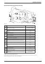
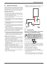
B Full port shutoff valves should be installed on both
the cold water supply and hot water outlet lines to
facilitate servicing the heater (see Fig. 26).
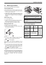
Note: If water flow or pressure is low, or heater does
not ignite, check the water inlet filter screen for debris
(see Chapter 5.1).
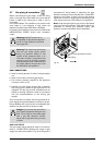
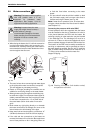
Connecting the pressure relief valve (PRV)
A listed pressure relief valve supplied with the heater
must be installed at the time of installation. No valve is
to be placed between the PRV and the heater. No
reducing coupling or other restriction may be installed
in the discharge line. The discharge line must be a
minimum of 4” above a drain and installed such that it
allows complete drainage of both the PRV and the line.
The location of the PRV must be readily accessible for
servicing or replacement, and be mounted as close to
the water heater as possible. See Fig. 26. To install the
PRV, a suitable fitting connected to an extension on a
“T” fitting can be sweated to the hot water line.
Support all piping.
Fig. 26 Plumbing connections (with isolation valves)
and pressure relief valve
Warning: This heater must be supplied
with cold potable water. It is not
approved for preheated water
applications. See chapter 3.12 for
approved recirculating application.
Warning: In areas where the water
supply has a high mineral content, a
water softener is strongly
recommended. Damage to the water
heater resulting from hard water/scale
deposits will not be covered under
warranty.
HOT
INLET
FILTER
COLD
UNION
(not sup-
plied with
heater)