


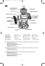
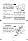
Bosch routers are designed for speed,
accuracy and convenience in performing
cabinet work, routing, fluting, beading, cove-
cutting, dove tails, etc. They will enable you
to accomplish inlay work, decorative edges
and many types of special carving.
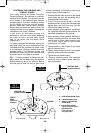
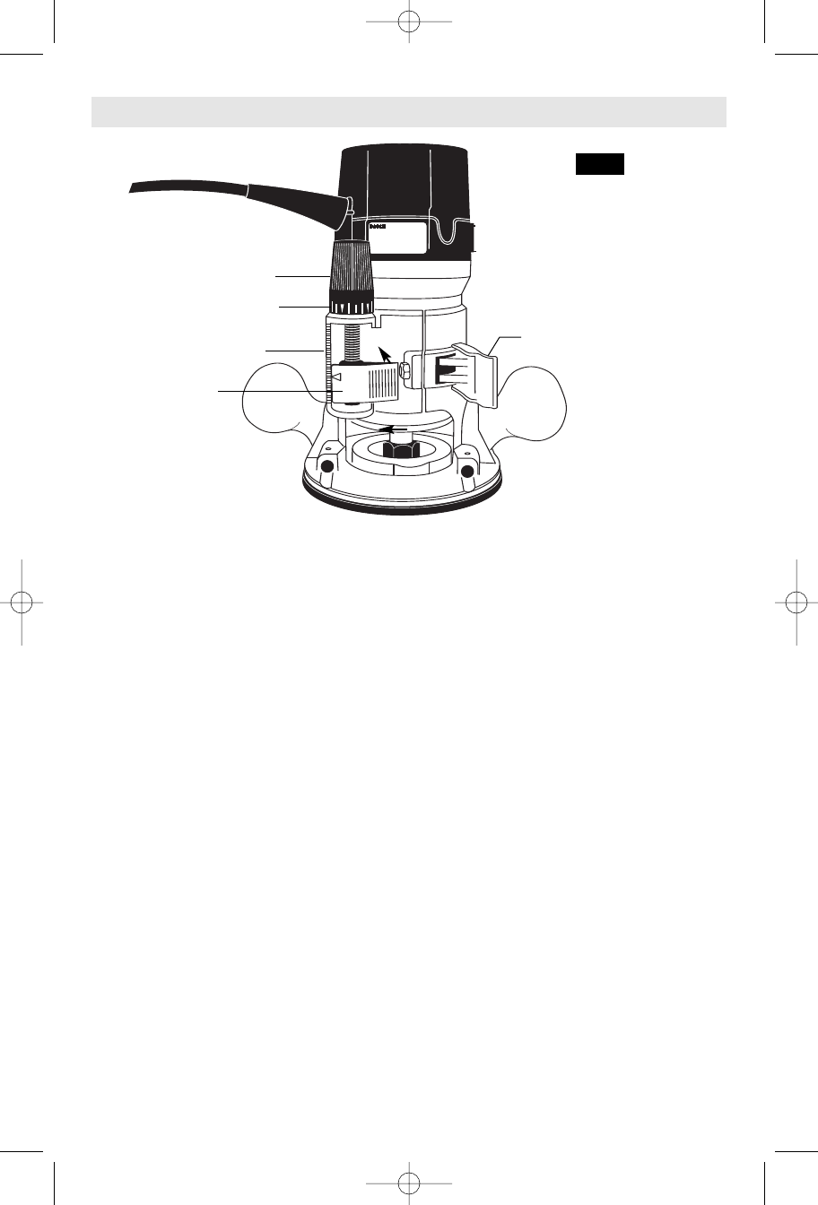
DEPTH ADJUSTMENT
WITH FIXED BASE
Your router is equipped with a true
micrometer type fine adjustment mechanism,
which can be used in any position and
provides precise adjustment of the router bit
position for unmatched accuracy. When the
tool is lowered to the approximate position
desired, this device may be adjusted to
precisely set the final bit position.
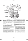
Your router also features three horizontal
notches on both sides of the motor housing
for coarse adjustments. The notches are
spaced 1/2" apart which allows you to quickly
lower or raise the tool depth in three 1/2"
increments. (Approximately 12.7 mm), by
simply depressing the coarse adjustment
release lever.
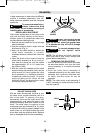
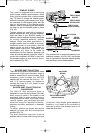
TO ADJUST DEPTH
NOTE:
All depth adjustments must be made
with the base clamp lever released.
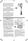
1. Hold the tool in a horizontal position with
the base clamp lever facing you.
2. Open the base clamp lever to release the
motor.
3. COARSE ADJUSTMENT:
To make a large depth adjustment, depress
coarse adjustment release lever and raise or
lower to desired depth. There are three
notches in the motor housing which are
spaced 1/2" to facilitate this adjustment.
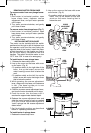
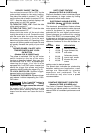
4. FINE DEPTH ADJUSTMENT:
To use the fine adjustment feature, turn the
fine adjustment knob clockwise to lower the
router bit or counter-clockwise to raise it.
NOTE: Be sure coarse adjustment lever is
engaged in one of the coarse adjustment
notches before making a fine adjustment.
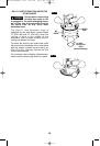
To allow precise settings, the indicator ring is
graduated in English and Metric increments.
(Note: one full turn of fine adjustment knob =
1/16" or approximately 1.5 mm. The fine
adjustment mechanism has a total
adjustment range of 7/8" (23 mm). Each cast
indicator mark next to coarse adjustment
lever is equal to 1/8"
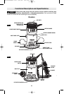
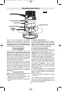
To prevent damage to tool, avoid wedging
the coarse adjustment lever against the
upper A or lower B portion of the housing as
shown in figure 11.
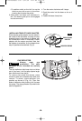
5. After making depth adjustments, re-clamp
the motor.
The indicator ring may be reset to zero
without moving the fine adjustment knob, to
allow the user to begin the adjustment from
any reference point desired.
-11-
Operating Instructions
A
B
FINE ADJUSTMENT DIAL
BASE CLAMP LEVER
COARSE
ADJUSTMENT
LEVER
INDICATOR RING
FIG. 11
CAST INDICATOR MARKS
BM 2610908996 6-04 6/21/04 4:47 PM Page 11