


USE IN ROUTER TABLE
Your router can also be used in a router
table. The RA1160 fixed base is designed to
allow easy depth adjustment in a table. The
RA1172 "D" D-Handle base will not fit in
most router tables.
The RA1166 Plunge Base
is not recommended for
use in a router table.
Damage to plunge
router base may occur.
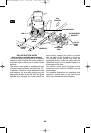
To install the RA1160 base in a table, simply
remove the sub-base and attach the base to
your router table using three 10-24 machine
screws or four 4 mm machine screws. The
length will depend on the thickness of your
router table or router table mounting plate.
For Bosch router tables, 3/4" or 20 mm is the
appropriate screw length.
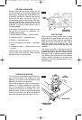
To eliminate the hassle of installing your
router’s own base on the router table and
later having to convert it back for non-table
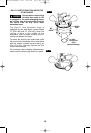
use, Bosch offers the optional RA1164
Undertable Router Base (Fig. 28). The
RA1164 base is designed to be permanently
attached your router table, leaving your other
router bases ready for non-table use. The
motor can be quickly moved from base to
base — without any tools!
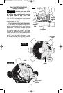
The undertable base accessory includes the
screws needed to fasten the base to a router
table mounting plate, as well as the fine
adjustment control extension (Fig. 12).
For complete instructions on operation of a
router in a router table and on the undertable
base, please refer to the instructions that
come with the router table and the undertable
base.
* The RA1172 “D” D-Handle base will not fit
in Bosch router tables.
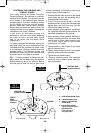
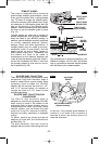
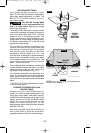
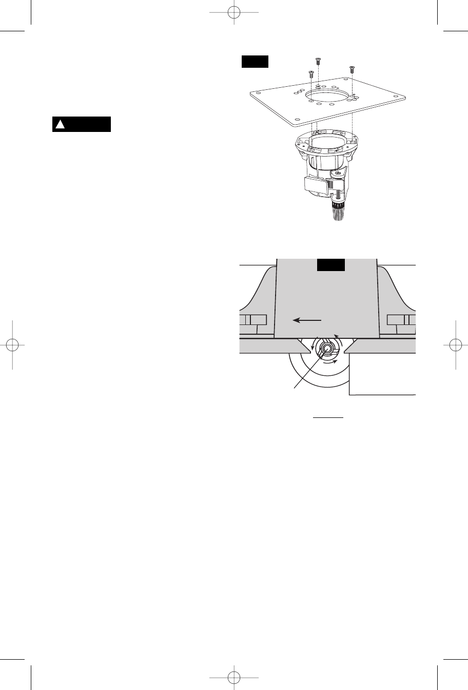
FEEDING THE WORKPIECE ON A
ROUTER TABLE
Always use your router table's fence or
starter pin and the appropriate guard and
follow the router table's instruction manual.
ALWAYS feed the workpiece from right to left
across the front of the bit. On Bosch router
tables, the correct feed direction is also
shown on fence housing and on the
featherboards, when they have been properly
installed. (Fig. 29)
Whenever possible, when using the fence,
use a push stick to push the workpiece,
especially when working with narrow pieces.
-21-
FIG. 29
WORKPIECE
DIRECTION
OF FEED
BIT
BEARING
TOP VIEW
NOTE: For clarity, guard and featherboard
removed from drawing.
FENCE FACE FENCE FACE
FIG. 28
OPTIONAL
RA1164
UNDERTABLE
ROUTER BASE
!
CAUTION
BM 2610908996 6-04 6/21/04 4:47 PM Page 21