


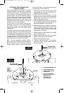
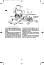
CENTERING THE SUB-BASE AND
TEMPLET GUIDES
Your router features the Bosch “Precision
Centering Design”. Its sub-base is precisely
centered at the factory. This positions the bit
at the center of the sub-base and optional
templet guides. Precision centering allows
you to closely follow jigs such as straight
guides, templets, and dovetail fixtures
without worrying about bit walk-off from the
intended cut line for any reason, including the
orientation of the router’s handles.
In the event the sub-base screws are
loosened or removed, such when preparing
the router for use in a router table, here's
how to re-center the sub-base when
reattaching it:
To quickly re-center the sub-base, attach the
sub-base using the set of flathead screws
(included) and the countersunk screw holes
in the sub-base. (Flathead screws have the
tapered heads.) The flathead screws and
countersunk holes will pull the sub-base into
a position that is very close to centered.
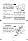
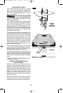
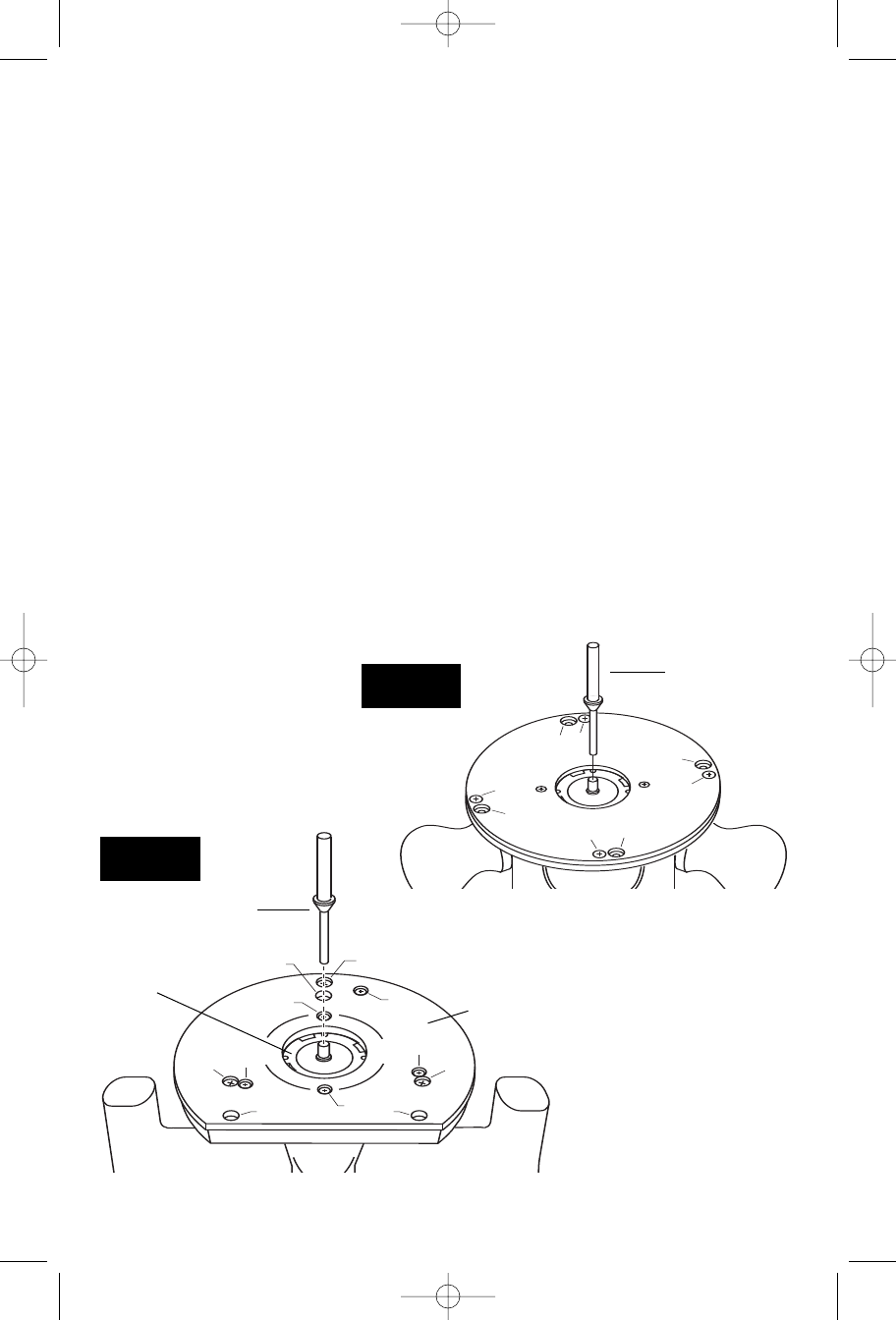
OR — To most precisely re-center the sub-
base, attach the sub-base using the optional
Bosch centering cone, an optional Bosch
templet guide, and the set of pan-head
screws (included). (Pan-head screws have
rounded tops.) Follow steps 1-8.
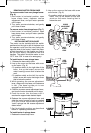
1. Position the sub-base so that its pan-head
screw holes are over the matching set of
threaded holes in the base.
2.Insert the pan-head screws, not the
flathead screws, through the sub-base and
tighten them until they are snug, but still
allow the sub-base to move.
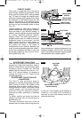
3. Insert templet guide (optional accessory)
the installed template guide adapter as
described elsewhere in this manual.
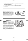
4. Slide centering cone (optional accessory)
through templet guide and into collet. Use
narrow end of cone when inserting into
1/4” collet, wider end of cone when
inserting into 1/2” collet.
5. Tighten collet nut with fingers to put slight
grip on centering cone.
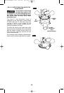
6. Lightly press centering cone into templet
guide to center guide and sub-base.
7. Tighten the pan-head screws.
8. Remove centering cone. The precision
centering of the templet guide and sub-
base is complete.
-16-
A
B
A
C
A
C
A
B
B
B
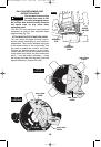
CENTERING CONE
(optional accessory)
D D
B
A
B
A
B
A
C
C
D
FIG. 17
PLUNGE BASE
FIG. 18
OTHER BASES
CENTERING CONE
(optional accessory)
TEMPLET
GUIDE
(optional
accessory)
SUB-BASE
A
= COUNTERSUNK SCREW HOLES
B = PAN-HEAD SCREW HOLES
C = TEMPLET GUIDE ADAPTER
SCREW HOLES
D = HOLES FOR ATTACHING
ROUTER TO ROUTER TABLE
MOUNTING PLATE
(Under sub-base on
non-plunge bases)
BM 2610908996 6-04 6/21/04 4:47 PM Page 16