


-12-
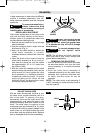
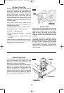
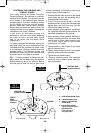
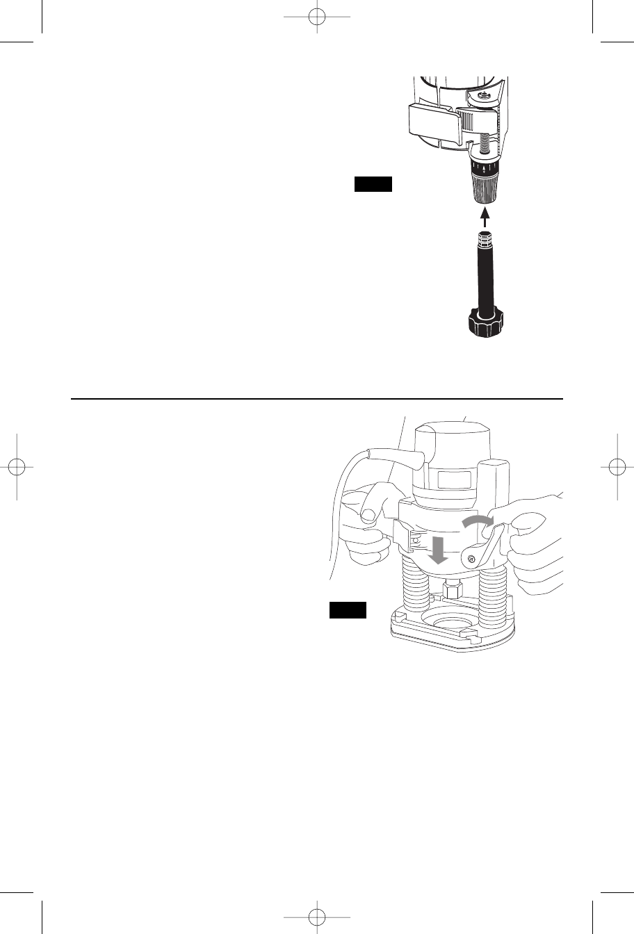
The RA1002 Fine Adjustment Control
Extension, an optional accessory for the non-
plunge bases, allows fine adjustment from
beyond the top of the motor housing. To
install, simply press the RA1002 into the end
of the base’s own fine adjustment knob.
(Fig. 12)
TO CLAMP MOTOR
When final coarse and fine adjustments have
been made, fasten the base clamp lever to
secure adjustments. (If additional clamping
force is desired: using a 10 mm wrench,
rotate clamp nut clockwise SLIGHTLY (1/8
turn or less), then test clamp. Do not over-
tighten.)
DEEP CUTS
For deeper cuts, make several progressively
deeper cuts by starting at one depth and
then make several subsequent passes,
increasing the cutting depth with each pass.
To be certain that your depth settings are as
desired, you may want to make test cuts in
scrap material before beginning work.
FIG. 12
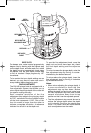
DEPTH ADJUSTMENT WITH PLUNGE BASE
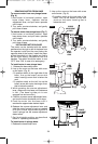
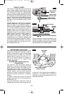
PLUNGING ACTION
The plunge feature simplifies depth
adjustments and will allow the cutting bit to
easily and accurately enter the workpiece. To
lower, push plunge lock lever to the left,
apply downward pressure until you reach
desired depth, and release pressure on lever
to lock (Fig. 13). The plunge lock lever is
spring loaded and returns automatically to
the locked position. To raise the router, push
plunge lock lever to the left, release pressure
on router and the router will automatically
retract the bit from the workpiece. It is
advisable to retract the bit whenever it is not
engaged in workpiece.
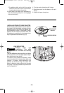
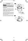
DEPTH ROD AND TURRET
The depth rod and the depth stop turret are
used to control cutting depth as follows;
1.With the bit installed, gently lower the
motor until the tip of the router bit just
contacts the level surface the router is
sitting on. This is the “zero” position, from
which further depth adjustments can be
accurately made.
2. To set a desired depth of cut, rotate depth
stop turret until the lowest step is aligned
with the depth rod. Loosen depth indicator
knob and lower the depth rod until it
contacts the lowest step of the turret. Slide
the depth indicator until the red line
indicates zero on the depth scale,
indicating the point at which the bit just
contacts the work (Fig. 14).
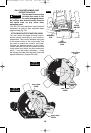
3.To set a desired cutting depth, slide the
depth rod up until the red depth indicator
line attains the desired cutting depth, and
secure the rod in position by firmly
tightening the depth indicator knob.
4.The desired depth of cut may now be
achieved by plunging the router until the
depth rod contacts the selected stop on
the turret.
FIG. 13
BM 2610908996 6-04 6/21/04 4:47 PM Page 12