


FP2000, FP2012
21 Sp
Manual de Instrucciones
Funcionamiento
(Continuación)
Cuando no haya fugas, el compresor
estará listo para funcionar.
VALVULA DE SEGURIDAD ASME
1. Esta válvula libera el aire del tanque
automáticamente si la presión excede
el nivel máximo fijado de fábrica.
¡Nunca
trate de
modificar esta válvula.
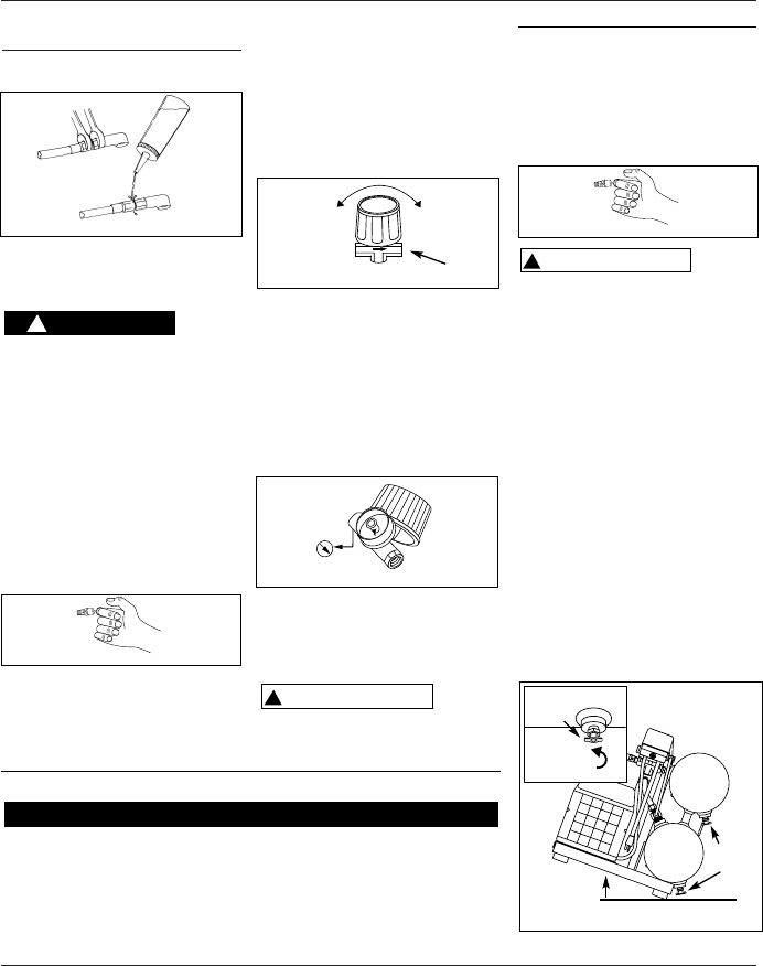
2. El funcionamiento de esta válvula
debe verificarse ocasionalmente
tirando del anillo con la mano. Es
posible que exista alguna fuga de aire
después de soltar el anillo. Sin
embargo, si la fuga continúa durante
un período de tiempo extenso, o si la
válvula de seguridad está trabada y no
se puede activar con el anillo, la
válvula de seguridad DEBE ser
reemplazada. (Nota: La válvula se
reajustará cuando la presión del
tanque alcance los 2.76 bar-3.45 bar.)
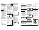
PERILLA DEL REGULADOR
1. Esta perilla controla la presión del
aire suministrado a las herramientas
neumáticas o pistolas
pulverizadoras.
!
PELIGRO
2. Gírela en el mismo sentido de las
agujas del reloj para aumentar la
presión de aire suministrado.
3. Gírela en sentido contrario a las
agujas del reloj para disminuir la
presión de aire suministrado.
4. Gírela completamente sentido
contrario a las agujas del reloj para
cerrar el flujo de aire
completamente.
MANOMETRO DE LA SALIDA
1. Este manómetro le permite verificar
rápidamente la presión del aire
suministrado. Esta presión se mide en
libras por pulgadas al cuadrado (PSI
por sus siglas en inglés).
2. Cerciórese de que este manómetro
esté en CERO antes de cambiar las
herramientas neumáticas o
desconectar la manguera de la
unidad.
MANOMETRO DEL TANQUE
Este manómetro le indica la presión del
tanque de aire y le permite verificar que
el compresor está funcionando
adecuadamente.
Desconecte el cordón eléctrico del
tomacorrientes y libere toda la presión
del sistema antes de hacer cualquier
reparación.
!
ADVERTENCIA
Mantenimiento
1. Chequée el compresor a ver si tiene
algún problema visible,
especialmente mídale el aceite para
verificar que esté lleno (en full).
2. Hale el anillo de la válvula de
seguridad y déjela que regrese a su
posición normal.
Debe
reem-
plazar la válvula de seguridad si no la
puiede activar o si tiene fugas de aire
después de soltar el anillo.
3. APAGUE la unidad y limpie el motor,
el tanque, las líneas de aire y las aletas
del sistema de enfriamiento del
cabezal.
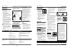
DRENE EL TANQUE
1. Diariamente debe drenar el tanque
con el compresor apagado: Para
hacerlo, abra las llaves de drenaje
ubicadas en la parte inferior de los
tanques.
2. Hay dos llaves de drenaje, una para
cada tanque. Gírelas en sentido
contrario a las agujas del reloj para
abrirlas.
3. Vire la unidad un poco para drenar el
líquido. Cuando vaya a tirar los
residuos de agua drenada del tanque
debe seguri las regulaciones locales al
respecto.
!
ADVERTENCIA
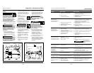
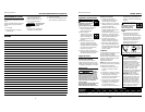
Figura 7
Figura 6
Figure 8
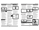
Para
Abrir
Para Cerrar
Para
Conectar la
Manguera
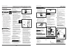
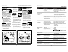
Drene el Tanque ●
Mídale el aceite ●
Chequée la Válvula de Seguridad ●
Cámbiele el Aceite ●
Límpiele el Filtro de Aire ● (Con más frecuencia
si hay mucho polvo
en el área de trabajo)
Mantenimiento Diariamente Mensualmente
MANTENIMIENTO NECESARIO
Figura 11
Vire la unidad
para drenar
los tanques
Llaves de
drenaje
Llave de
drenaje
Figura 9
Para Abrir
Figura 10
4
Operating Instructions
Oil Lubricated Portable Air Compressor
Preparation (Cont.)
2. If repair or replacement of cord or
plug is necessary, do not connect
grounding wire to either flat blade
terminal. The grounding wire has
insulation and an outer surface that
is green with or without yellow
stripes.
3. Check with a qualified electrician or
serviceman to ensure product is
properly grounded. Do not modify
plug provided; if plug will not fit
outlet, have proper outlet installed
by a qualified electrician.
Never connect
green (or green and
yellow) wire to a live terminal.
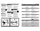
EXTENSION CORDS
Avoid using an extension cord. To extend
the reach of the compressor, additional
air hose is recommended.
1. Use only a 3-wire extension cord
that has a 3-blade grounding plug,
and a 3-slot receptacle that will
accept plug on product.
2. Make sure extension cord is in good
condition, and heavy enough to carry
current product will draw. An
undersized cord will cause a drop in
line voltage resulting in loss of power
and overheating.
3. The chart on page 3 shows correct
size to use depending on cord length
and nameplate ampere rating. If in
doubt, use next heavier gauge.
NOTE: The smaller the gauge number,
the heavier the cord.
Operation
FOR TROUBLE-FREE OPERATION
1. Keep compressor level during
operation and while checking oil
level.
2. Check oil level before each use. Add
oil to full line on the dipstick.
Operation with low oil will damage
pump and may cause difficulty in
starting.
3. Read instructions: Carefully read
through this owner’s manual BEFORE
OPERATING the new air compressor.
!
WARNING
It contains information
about operation and
maintenance of unit.
4. Drain tank daily: Open
drain cocks and tilt unit
to drain moisture from tanks (See
Figure 12). Be sure to close drain cocks
tightly before operating compressor.
This helps prevent tank corrosion and
keeps oil and moisture out of
compressed air.
5. Check air filter: Never run compressor
without an air filter nor with a
clogged air filter. See maintenance
section for cleaning and replacement
instructions.
BREAK-IN
Break-in: Allow new compressor to run
for at least 30 minutes without
compressing air, to properly seat working
parts.
Do not attach air
chuck or other tool
to open end of hose until start-up has
been completed and unit checks OK.
1. Turn regulator knob fully clockwise.
2. Turn switch or knob to OFF position,
and plug in power cord.
3. Turn switch or knob to AUTO position
and run unit for 30 minutes to break
in pump parts.
!
CAUTION
4. Turn regulator knob fully
counterclockwise. Compressor will
build to maximum preset pressure and
shut off.
5. Turn regulator knob clockwise to
cause air to bleed off. Compressor will
restart at present pressure.
6. Turn regulator knob counterclockwise
to shut off air and turn switch to OFF
position.
7. Attach air chuck or other tool to open
end of hose. Turn regulator fully ON.
Apply a soap and water solution
around hose fittings and check for
signs of leaks (bubbles forming). If
there is a leak, tighten connections
and check again. When there are no
leaks, compressor is ready for
operation.
ASME SAFETY VALVE
1. This valve automatically releases air
if air receiver pressure exceeds
preset maximum.
Do not attempt to
tamper with this
valve!
2. This valve should be checked
occasionally by pulling the ring by
hand. Air may leak even after ring
has been released. However, if the
leaking continues for an extended
period of time, or if the safety valve is
stuck and cannot be activated by the
ring, the safety valve MUST be
replaced. (Note: Valve will reset when
tank pressure reaches 40-50 PSI.)
REGULATOR KNOB
1. This knob controls air pressure to an
air operated tool, or paint spray
gun.
!
DANGER
A
U
T
O
/
O
F
F
Figure 4
Figure 7
Figure 5
Figure 6
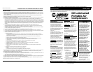
Close
Open
Attach
Hose
Air Flow
MANUAL
AUTO position
OFF position
www.chpower.com