


General Safety
(Continued)
Arc
welding closed cylinders
or containers such as
tanks or drums can cause
explosion if not properly
vented! Verify that any
cylinder or container to be welded has
an adequate ventilation hole, so that
expanding gases can be released.
Do
not breathe fumes that
are produced by the arc
welding operation. These
fumes are dangerous. If
the welding area cannot
be adequately ventilated, be sure to use
an air-supplied respirator.
● Keep the head and face out of the
welding fumes.
● Do not perform electric arc welding
operations on metals that are
galvanized or cadmium plated, or
contain zinc, mercury, or beryllium
without completing the following
precautions:
a. Remove the coating from the base
metal.
b. Make sure that the welding area is
well ventilated.
c. Use an air-supplied respirator.
Extremely toxic fumes are created
when these metals are heated.
The
electromagnetic field that
is generated during arc
welding may interfere
with the operation of
various electrical and
electronic devices such as cardiac
pacemakers. Persons using such devices
should consult with their physician prior
to performing any electric arc welding
operations.
● Route the wire gun and work cables
together and secure with tape when
possible.
● Never wrap arc welder cables around
the body.
● Always position the wire gun and
work leads so that they are on the
same side of the body.
● Exposure to electromagnetic fields
during welding may have other
health effects which are not known.
Always be sure
that the welding
area is secure and free of hazards
(sparks, flames, glowing metal or slag)
prior to leaving. Be sure that equipment
is turned off and excess wire is cut off.
Be sure that cables are loosely coiled and
out of the way. Be sure that all metal
and slag has cooled.
!
WARNING
!
WARNING
!
WARNING
!
WARNING
significantly degrade the
performance of the welder.
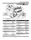
Assembly -
WF1800/WF1900
All welding accessories for the
welder are inside the wire feed
compartment. Lift wire feed cover
to find handle, workclamp, etc.
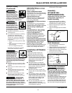
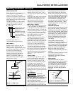
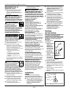
Handle Assembly
1. Place handle assembly on welder,
aligning two holes in the ends with
threaded holes in welder housing.
2. Fasten screws through handle ends
and into cabinet.
3. Insert cord storage clips into handle
ends.
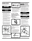
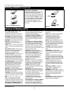
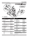
Shaft Attachment
1. Open up the panel to expose the
wire feed platform.
2. Align the shaft hole and notch to the
welder screw hole and notch hole.
3. Fasten with screw down through the
shaft and into the welder.
4. Press spring into top of spindle.
Flux Core Wire Installation
Welding power
may be applied to
the output terminals, feed roll, work
clamp, gun cable connection and welding
wire even when the the gun switch is not
activated. Do not touch these parts when
the welding machine is on.
Note: Before installing welding wire, be
sure that the diameter of the welding
wire matches the groove in the drive
roller on the wire feed mechanism and
that the wire size matches the contact
tip in the end of the gun (see Figure 5).
!
WARNING
3
ADDITIONAL SAFETY STANDARDS
ANSI Standard Z49.1 from American
Welding Society, 550 N.W. Le June Rd.
Miami, FL 33126
Safety and Health Standards
OSHA 29 CFR 1910, from Superintendent
of Documents, U.S. Government Printing
Office, Washington, D.C. 20402
National Electrical Code
NFPA Standard 70, from National Fire
Protection Association, Batterymarch
Park, Quincy, MA 02269
Safe Handling of Compressed Gases
in Cylinders
CGA Pamphlet P-1, from Compressed
Gas Association, 1235 Jefferson Davis
Highway, Suite 501, Arlington, VA 22202
Code for Safety in Welding and
Cutting
CSA Standard W117.2, from Canadian
Standards Association, Standards Sales,
178 Rexdale Boulevard, Rexdale,
Ontario, Canada M9W 1R3
Cutting And Welding Processes
NFPA Standard 51B, from National Fire
Protection Association, Batterymarch
Park, Quincy, MA 02269
Safe Practices For Occupational And
Educational Eye And Face Protection
ANSI Standard Z87.1, from American
National Standards Institute, 1430
Broadway, New York, NY 10018
Refer to the Material Safety Data Sheets
and the manufacturers instructions for
metals, wire, coatings and cleaners.
Installation (All Models)
LOCATION
Selecting the proper location can
significantly increase performance,
reliability and life of the arc welder.
● For best results locate the welder in
an environment that is clean and dry.
Dust and dirt in the welder retain
moisture and increase wear of
moving parts.
● Place the welder in an area that
provides at least twelve inches (305
mm) of ventilation space at both the
front and rear of the unit. Keep all
obstructions away from this
ventilation space.
● Store flux core wire in a clean, dry
location with low humidity to reduce
oxidation.
● The receptacle used for the welder
must be properly grounded and the
welder must be the only load on the
power supply circuit. Refer to the
Circuit Amps chart on page 1 for
correct circuit capacity.
● The use of an extension cord is not
recommended for electric arc
welding machines. The voltage drop
in the extension cord may
Models WF1800, WF1900 and WF2000
U
T
IL
IT
Y
UTILITY
W
E
L
D
E
R
WELDER
W
O
R
K
C
L
A
M
P
WORK CLAMP
1
1
5
V
O
L
115 VOL
T
6
0
H
Z
60HZ
Figure 2 - Handle Assembly
Cord Storage
Clip
Cord
Storage
Clip
Figure 3 - Shaft Attachment Assembly
Spindle
Attachment
Screw
Spindle
Spring
www.chpower.com