


35 Sp
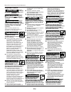
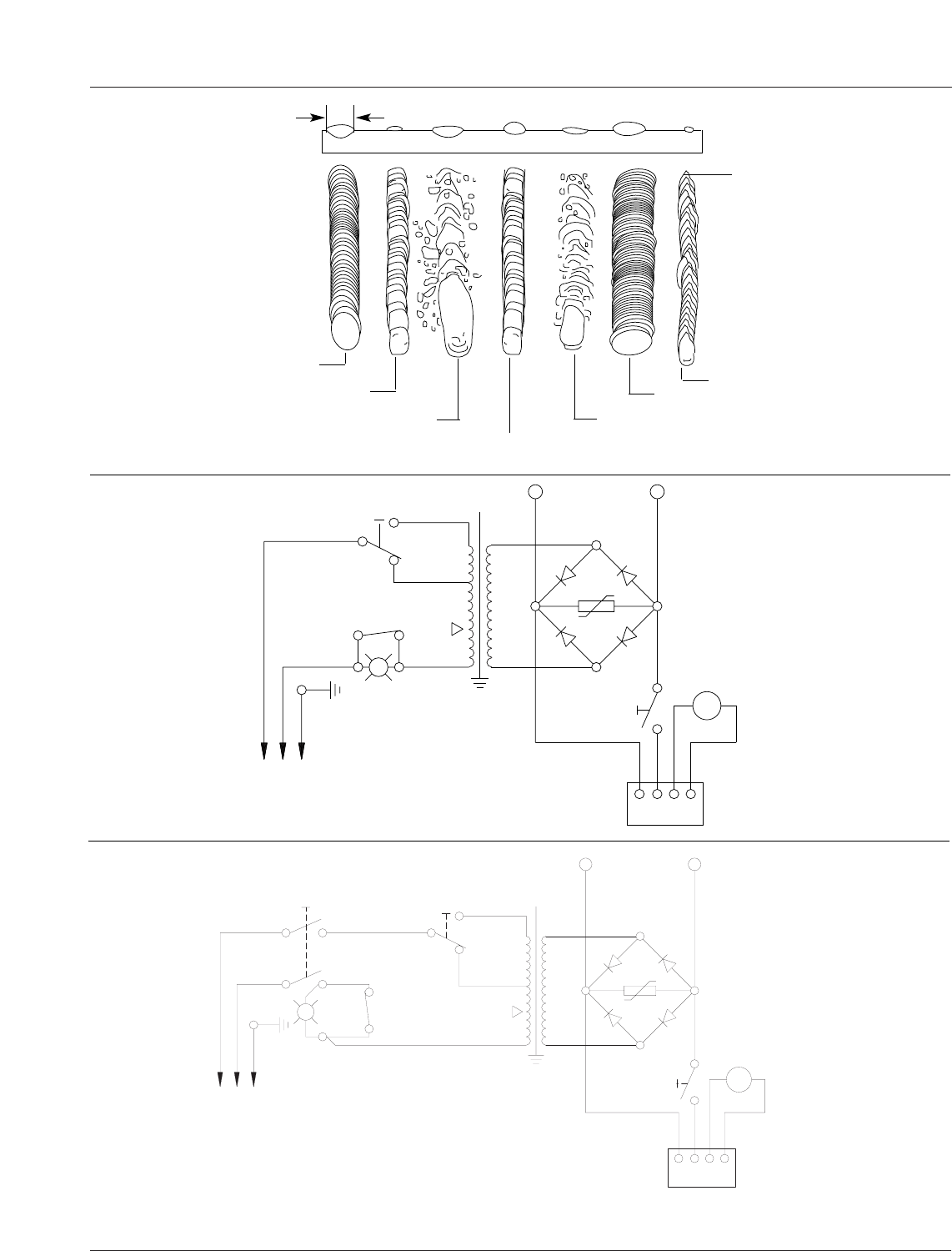
Metal Básico
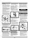
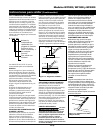
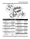
Figura 17 - Apariencia de la soldadura
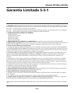
Y
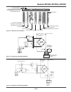
S4 NC
ABRE A @ 127∞C
TIERRA
MIN
MAX
T1
S2
NEGRO
BLANCO
VERDE
~
+
-
S4
-+
M
UNIDAD DE
ALIMENTACIÓN
DE ALAMBRE
-
+
4321
TABLERO DE
CONTROL DE
VELOCIDAD DEL
ALAMBRE
~
S3
PISTOLA
1
2
4
5
6
L2
L1
PARA LA PINZA
DE CONEXIÓN A
LA PIEZA
PARA LA SOPLETE
ENCENDIDO/APAGADO
S1
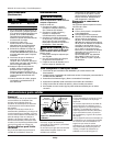
Figura 19 - Esquema del alambrado (WF2000)
Velocidad de alimentación muy rápida
Corriente muy alta
Velocidad de desplazamiento muy lenta
Corriente muy baja
Velocidad muy lenta
Velocidad muy rápida
Corriente, velocidad de
alimentación y velocidad de
desplazamiento normales
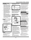
A
Nota: El ancho (A) del
reborde debe ser
aproximadamente el doble
del diámetro de la varilla de
electrodo que se use.
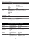
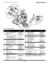
Modelos WF1800, WF1900 y WF2000
S3
APAGADO
L2
L1
PISTOLA
S2
~
TARJETA DE CONTROL
DE VELOCIDAD DEL
ALAMBRE
1234
+
-
UNIDAD DE
ALIMENTACIÓN
DE ALAMBRE
M
+
+
-
-
-
+
~
VERDE
BLANCO
NEGRO
S1
T1
MAX
MIN
TIERRA
S3 NC
ABRE A 120˚C
Y
PARA LA SOPLETE
PARA LA PINZA
DE CONEXIÓN A
LA PIEZA
Figura 18 - Esquema del alambrado (WF1800)