


7. Turn on the welder and activate the
gun switch until the wire feeds out
past the torch end. Turn welder off.
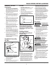
8. Carefully slip the contact tip over the
wire and screw it into the torch end.
Install the nozzle by turning
clockwise. (See Figure 5). Cut the
wire off approximately 1/4 inch from
the end of the nozzle.
Assembly - WF2000
All welding accessories for the
welder are inside the wire feed
compartment. Lift and remove wire
feed cover to find handle,
workclamp, etc.
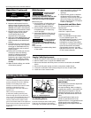
Handle Assembly
1. Slide handle into plastic ends as
shown (Fig. 6).
2. Place handle assembly on welder
aligning two holes in plastic ends
with threaded holes in welder
housing.
3. Fasten screws through handle ends
and into cabinet.
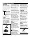
WORK CLAMP
1. Loosen hex bolt on work clamp.
2. Insert cord (labeled work on the
front panel of the welder) through
clamp handle and slide bare wire
under the clamp block. Tighten hex
bolt making sure bare wire is
clamped securely (Fig. 7).
4
Operating Instructions and Parts Manual
Assembly - WF1800/
WF1900 (Continued)
Any mismatch could cause the wire to
slip, bind or weld poorly.
1. Verify the unit is off and lift the
panel on the welder to expose the
wire feed mechanism.
2. Loosen the wire feed tensioning
screw on the drive mechanism. This
allows initial feeding of the wire into
the gun liner by hand.
3. Install the wire spool onto the
spindle so that the wire can come off
the spool on the end closest to the
wire feed guide tube. Do not cut
the wire loose yet.
4. Hold the wire and cut the wire end
from the spool. Do not allow the
wire to unravel. Be sure that the end
of the wire is straight and free of
burrs.
5. Feed the wire through the wire feed
guide tube, over the groove in the
drive roll and into the gun liner.
Tighten the wire feed tensioning
screw so that it is snug. Do not over
tighten. Close the wire feed panel.
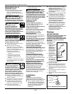
6. Remove the nozzle by turning
counter-clockwise. Then unscrew the
contact tip from the end of the
welding torch (See Figure 5). Plug
the welder into the proper power
supply receptacle.
Flux Core Wire Installation
Welding power
may be applied to
the output terminals, feed roll, work
clamp, gun cable connection and welding
wire even when the the gun switch is not
activated. Do not touch these parts when
the welding machine is on.
Note: Before installing welding wire, be
sure that the diameter of the welding
wire matches the groove in the drive
roller on the wire feed mechanism and
that the wire size matches the contact
tip in the end of the gun (see Figure 5).
Any mismatch could cause the wire to
slip, bind or weld poorly.
1. Verify the unit is off and lift the
panel on the welder to expose the
wire feed mechanism.
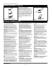
2. Remove the spool quick lock by
pushing in and rotating 1/4 turn
counterclockwise. The knob, spring,
and spool spacer can now be
removed.
3. Loosen the wire feed tensioning
screw on the drive mechanism. This
allows initial feeding of the wire into
the gun liner by hand.
4. Install the wire spool onto the
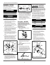
spindle so that the wire can come off
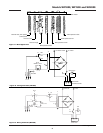
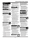
!
WARNING
Wire Flux
Core
Pan Head Screws
Swing
Arm
Tension
Screw
Tension
Spring
Spindle
Roller
Figure 4 - Weld Wire Routing
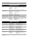
Contact Tip Markings
Mark Wire Size
0.8 0.030”
0.9 0.035”
1
1
5
V
O
L
T
G
R
O
U
N
D
6
0
H
Z
2
3
A
0
1
2
3
4
5
6
7
8
9
1
0
N
O
R
M
A
L
O
P
E
R
A
T
I
N
G
R
A
N
G
E
S
I
N
G
L
E
P
H
A
S
E
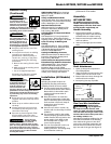
WF2000
O
N
O
F
F
L
O
W
H
I
G
H
H
E
A
T
S
E
L
E
C
T
O
R
W
I
R
E
S
P
E
E
D
L
O
W
5
5
A
C
1
7
2
5
%
4
2
H
I
G
H
6
5
A
C
1
8
2
0
%
4
4
H
E
A
T
S
E
T
T
I
N
G
W
E
L
D
I
N
G
A
M
P
S
W
E
L
D
I
N
G
V
O
L
T
S
D
U
T
Y
C
Y
C
L
E
M
A
X
O
C
V
Figure 6 - Handle Assembly
Figure 7 - Work Clamp Assembly
Contact Tip Markings
Mark Wire Size
0.8 0.030”
0.9 0.035”
Wire Size Chart
Inches mm
0.030 0.8
0.035 0.9
Wire Size Chart
Inches mm
0.030 0.8
0.035 0.9
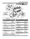
Drive
Roller
Spool
Lock
Tension
Screw
Panel
Spring
Figure 8 - Weld Wire Routing
Spool
Spacer
Spindle
Guide
Tube
www.chpower.com
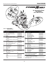
Torch
Diffuser
Contact Tip
Nozzle
Figure 5 - Torch Nozzle