


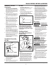
Arc Welding Basics
Five basic techniques affect weld quality.
These are: wire selection, heat setting,
weld angle, wire speed, and travel speed.
6
Operating Instructions and Parts Manual
General
This line of welding machines utilizes a
process called Flux Cored Arc Welding
(FCAW). The FCAW process uses a
tubular wire with a flux material inside.
Shielding is obtained from the
decomposition of the flux within the
tubular wire.
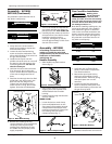
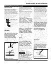
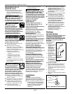
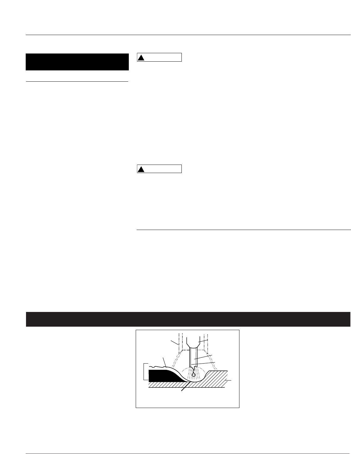
When current is produced by a
transformer (welding machine) and
flows through the circuit to the weld
wire, an arc is formed between the end
of the weld wire and the work piece.
This arc melts the wire and the work
piece. The melted metal of the weld wire
flows into the molten crater and forms a
bond with the work piece as shown in
Figure 12.
Welding Guidelines
An understanding of these techniques is
necessary for effective welds.
HEAT SETTING
The correct heat involves the adjustment
of the welding machine to
the required setting. Heat or voltage is
regulated by a switch on the welder. The
heat setting used depends on the size
(diameter) and type of wire, position of
the weld, and the thickness of the work
piece.
Consult specifications listed on the
welder or generalized chart in the
Operation section. It is suggested that the
welder practice with scrap metal to
adjust settings, and compare welds with
Figure 17.
Operation (Continued)
6. Rotate the Wire Speed Control to
setting number 5 to start with, then
adjust as needed after test weld. The
WF1800’s wire speed is automatically
adjusted to the heat selection chosen.
7. Plug the input cord into a proper
voltage receptacle with proper
circuit capacity (See circuit
requirements on front page).
8. Switch the welder ON/OFF switch to the
ON position. For the WF1800/WF1900,
switch the welder to the desired heat
setting.
9. Verify that the wire is extended 1/4”
from the contact tip. If not, squeeze
the trigger to feed additional wire,
release the trigger, and cut wire to
proper length.
10. Position the wire feed gun near the
work piece, lower the welding
helmet by nodding the head, or
position the hand shield, and
squeeze the gun trigger. Adjust heat
setting and wire speed as needed.
Wire speed is not adjustable on the
WF1800.
11. When finished welding, turn welder
off and store properly.
Maintenance
Disconnect power
supply and turn
machine off before inspecting or
servicing any components. Keep the wire
compartment cover closed at all times
unless the wire needs to be changed.
Before every use:
1. Check condition of weld cables and
immediately repair or replace any
cables with damaged insulation.
2. Check condition of power cord and
immediately repair or replace any
cord if damaged.
3. Inspect the condition of the gun tip
and nozzle. Remove any weld slag.
Replace gun tip or nozzle if
damaged.
Do not operate this
welding machine
with cracked or missing insulation on
welding cables, wire feed gun, or power
cord.
Every 3 months:
1. Replace any unreadable safety labels
on the welder.
!
WARNING
!
WARNING
2. Use compressed air to blow all dust
and lint from the ventilation
openings.
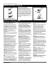
3. Clean the wire groove on the drive
roll. Remove wire from the feed
mechanism, remove screws from the
drive roll housing. Use a small wire
brush to clean the drive roll. Replace
if worn or damaged
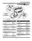
Consumable and Wear Parts
The following parts require routine
maintenance:
• Wire feed drive roller
• Gun liner - replace if worn
• Nozzle/contact tips
• Wire - The WF2000 will accept either
4” or 8” diameter spools. The
WF1800/WF1900 will accept 4” spools
only. Flux-cored welding wire is
susceptible to moisture and oxidizes
over time, so it is important to select a
spool size that will be used within
approximately 6 months. Use AWS
type E71T-GS or E71T-11, .030” (.8mm)
or .035” (.9mm) diameter.
Metal Heat
Thickness Setting
14 - 18 Gauge Low
Thicker Than 14 Gauge High
Supply Cable Replacement
1. Verify that welder is OFF and power cord disconnected.
2. Remove welder cover to expose the ON/OFF switch.
3. Disconnect the black and white power cord wires connected to the ON/OFF
switch.
4. Disconnect the green power cord wire connected to welder frame.
5. Loosen the cord strain relief screw(s) and pull cord out of strain relief.
6. Install new cord in reverse order.
Slag
Weld
Wire
Flux
Work Piece
Diffuser
Nozzle
Contact
Tip
Crater
www.chpower.com
Figure 12 - Weld Components