


5
Assembly - WF2000
(Continued)
the spool on the end closest to the
wire feed guide tube. Do not cut
the wire loose yet. Install the spool
spacer, spring, and quick lock knob
by pushing in and turning the knob
1/4 rotation clockwise.
5. Hold the wire and cut the wire end
from the spool. Do not allow the
wire to unravel. Be sure that the end
of the wire is straight and free of
burrs.
6. Feed the wire through the wire feed
guide tube, over the groove in the
drive roll and into the gun liner.
Tighten the wire feed tensioning
screw so that it is snug. Do not over
tighten. Install the outer welder
panel.
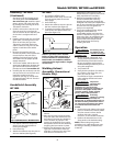
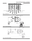
7. Remove the nozzle by turning
counter-clockwise. Then unscrew the
contact tip from the end of the
welding torch (See Figure 5). Plug
the welder into the proper power
supply receptacle.
8. Turn on the welder and set the wire
speed rate to Maximum. Activate the
gun switch until the wire feeds out
past the torch end. Turn welder off.
9. Carefully slip the contact tip over the
wire and screw it into the torch end.
Install the nozzle by turning
clockwise. (See Fig. 5). Cut the wire
off approximately 1/4 inch from the
end of the nozzle.
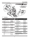
Handshield Assembly
WF1800
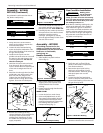
1. Cut retainer stiffeners away from
shield. Trim the excess plastic to
remove sharp edges.
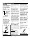
2. Insert filter lens.
3. Attach the stiffeners over the pins on
the lens retainers (See Figure 9).
WF2000
1. Cut retainer stiffeners and
detachable handle away from shield.
Trim the excess plastic to remove
sharp edges.
2. Insert filter lens.
3. Attach the stiffeners over the pins on
the lens retainers (See Figure 9).
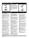
4. To attach the handle, place shield on
a flat surface and press handle into
place (See Figure 10).
NOTE: If you have never welded
before or have little experience, a
full face helmet is recommended.
Both hands are needed to stabilize
and control the angle and arc length
of the torch.
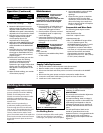
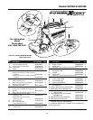
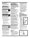
Welding Helmet
Assembly
(Promotional
Models Only)
1. Remove the lens retainer from the
helmet.
2. Place the clear lens into the helmet
first, then place the shaded lens into
the helmet. The clear lens should be
on the outside. Its purpose is the
protect the shaded lens from sparks
and spatter. Secure the two lenses by
snapping the lens retainer in place.
3. Position the adjustment arm on the
right side of the helmet. Place the
small pin on the arm into one of the
small holes in the helmet. This
adjustment controls the fit of the
helmet when it is lowered, and can be
easily repositioned if necessary.
4. Position the headgear inside the
helmet. Assemble the helmet by
inserting the stud screw through the
headgear and helmet (and adjustment
arm on the right side) into the tension
nut as shown. Do not tighten the
tension nut completely.
5. Trial fit the welding helmet. Adjust
headgear ratchet band to a
comfortable position and lower the
helmet. If the helmet is too far or too
close to the face, use a different hole
for the adjustment arm. Adjust the
tension nuts so the helmet can be
easily lowered over the face by
nodding the head.
Operation
The welding wire is
live whenever the
welder is turned on - whether the trigger
is pulled or not.
1. Be sure to read, understand, and
comply with all precautions in the
General Safety Information section.
Be sure to read the entire section
entitled Welding Guidelines prior to
using this equipment.
2. Turn welder off.
3. Verify that the surfaces of metals to
be joined are free from dirt, rust,
paint, oil, scale or other
contaminants. These contaminants
make welding difficult and cause
poor welds.
All persons
operating this
equipment or in the area while
equipment is in use must wear
protective welding gear including: eye
protection with proper shade, flame
resistant clothing, leather welding
gloves, and full foot protection.
If heating,
welding, or cutting
materials that are galvanized, zinc
plated, lead, or cadmium plated refer to
the General Safety Information Section
for instructions. Extremely toxic fumes
are created when these metals are
heated.
4. Connect the work clamp to the work
piece or workbench (if metal). Make
sure the contact is secure. Avoid
surfaces with paint, varnish,
corrosion, or non-metallic materials.
5. Position the Heat Selector on the
front panel to the desired setting.
NOTE: These settings are general
guidelines only. Heat setting may vary
according to welding conditions and
materials.
!
WARNING
!
WARNING
!
CAUTION
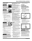
Models WF1800, WF1900 and WF2000
Figure 11
Headgear
Face
Shield
Shaded Lens
Clear Lens
Lens Retainer
Adjustment
Arm
Tension
Nut
Stud Screw
Figure 9 (WF2000 shown - WF1800 similar)
Lens
Lens
Retainer
Retainer
Stiffener
Figure 10
www.chpower.com