


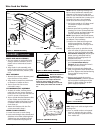
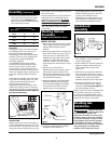
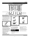
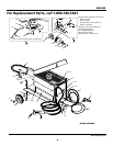


WHEEL AND AXLE ASSEMBLY
1. Put one wheel on each end of axle
Using a mallet or hammer, drive a
plastic hub on axle ends to secure
wheels.
2. Align holes in axle assembly with
holes in base plate at rear of welder.
Secure with two bolts, washers, and
nuts.
FOOT ASSEMBLY
1. Remove four screws in bottom panel
near the front of the welder.
2. Align holes in metal foot with holes
on bottom of welder at front.
3. Secure foot with four screws
removed in step 1.
CYLINDER BRACKET ASSEMBLY
1. At back of welder, halfway down
each side, are two screws. Remove
both pairs of screws. Also remove the
screw in center of back panel.
2. Insert cylinder bracket between sides
of the welder and its black back,
aligning its holes with those in sides
of welder. Make sure bracket has
chain slots up.
3. Attach the bracket with the five
screws removed in Step 1.
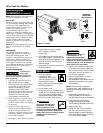
WORK CLAMP ASSEMBLY
1. Loosen hex nuts on work clamp.
2. Insert cord through clamp handle and
slide bare wire under clamping block.
Tighten hex nuts, making sure bare
wire is clamped securely (Figure 3).
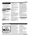
WIRE INSTALLATION
When the welder is
on and the gun
switch is activated, electric power may
be present in the output terminals,
feed roll, work clamp, gun cable
connection and welding wire. Do not
touch these parts when the welder is
on.
4
Wire Feed Arc Welder
NOTE: Before installing welding wire,
be sure that its diameter matches the
diameter of the groove in the drive
roller on the wire feed mechanism and
that the wire matches the contact tip in
the end of the gun. Any mismatch
could cause the wire to slip or bind.
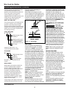
1. Verify that welder is off. Open panel
on welder to expose wire feed
mechanism.
2. Remove spool lock by pushing in and
rotating it a 1/4 turn counterclockwise.
The knob, spring, and spool spacer can
now be removed. (See Figure 4).
NOTE: Spool spacer and spindle spacer
act as an 8” spool adapter. Purchase of
an adapter is not necessary.
3. Loosen wire feed tensioning screw
on drive mechanism. This allows
initial feeding of wire into gun liner
by hand.
4. Place wire spool on spindle so that
wire will come off spool on the end
closest to wire feed guide tube. Do
not cut wire loose yet. Install spool
spacer, spring, and spool lock by
pushing in and turning knob 1/4
rotation clockwise.
5. Hold wire and cut wire end from
spool. Do not allow wire to
unravel. Be sure that end of wire is
straight and free of burrs.
6. Feed wire through wire feed guide
tube, over groove in drive roll and into
gun liner. Tighten wire feed tensioning
screw so that it is snug. Do not
overtighten.
7. Remove torch nozzle by turning
counterclockwise. Unscrew contact
tip from end of welding torch (See
Figure 5). Plug welder into proper
power supply receptacle.
HINT: Keep torch cable straight when
feeding wire.
8. Turn on welder and set wire speed
rate to 5. Activate the gun switch
until wire feeds out past torch end.
Turn welder off.
Assembly
(Continued)
www.chpower.com
Clamping
Block
Figure 3 - Work Clamp Assembly
Torch Neck
Contact Tip
Nozzle
Figure 5 - Torch Nozzle
Figure 2 - WG4000 Assembly
Figure 4 - Weld Wire Routing
Bolt
Washer
Nut
Axle
Plastic
hub
Wheel
Hex Nuts
Cord
Foot
assembly
Bolt
Cylinder
chain
Cylinder
bracket
!
WARNING