


6
Wire Feed Arc Welder
NOTE: Shielding gas is not required if
flux-cored welding wire is used.
GAS TYPES
There are 3 types of gas generally used
for gas metal arc welding; 100% argon,
a mixture of 75% argon and 25%
carbon dioxide (C25) or 100% carbon
dioxide. The 75/25 mixture is
recommended for general steel
welding. For aluminum welding, use
100% argon. Cylinders of each type gas
may be obtained at your local welding
supply outlet. Secure cylinder in place
on your welding machine or other
support to prevent the cylinder from
falling over.
NOTE: Use of incorrect gas may lead to
little or no penetration of welding
bead.
REGULATOR
The regulator provides a constant
shielding gas pressure and flow rate
during the welding process. Each
regulator is designed to be used with a
specific gas or mixture of gases. The
argon and argon mixture use the same
thread type. The 100% carbon dioxide
uses a different thread type. An adapter
is included with this unit to change
between the two.
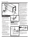
HOOKUP PROCEDURE
Cylinder gas is
under high
pressure. Point cylinder outlet away
from yourself and any bystanders
before opening.
1. A 20 cubic ft bottle fits this unit.
2. With cylinder securely installed,
remove cylinder cap, stand to side of
the cylinder opposite outlet, and
open the valve slightly, turning
counterclockwise. When gas is
emitted from the cylinder, close valve
by turning clockwise. This will blow
out dust or dirt that may have
accumulated around valve seat.
3. Install regulator on cylinder valve,
keeping face of gauges in vertical
position. Tighten stem nut securely
to gas valve.
4. Install one end of gas hose on
fitting on rear of welder and the
other end to the fitting on the
regulator. Use hose clamps on each
connection. Make sure gas hose is
not kinked or twisted.
5. Once again, stand opposite cylinder
!
WARNING
outlet and slowly open cylinder
valve. Inspect for leaks in
connections.
6. Pull trigger on gun to allow gas to
flow. While trigger is pulled and gas
is flowing, adjust gas regulator to at
least 20 cfh (cubic feet per hour).
Release trigger.
7. Remember to close gas valve when
finished welding.
1. Prior to using this
equipment, read,
understand, and comply
with all precautions in the
General Safety section.
Also, read the entire section titled
Welding Guidelines.
2. Verify welder is off.
3. Verify that surfaces of metals to be
joined are free from dirt, rust, paint,
oil, scale or other contaminants.
These contaminants make welding
difficult and cause poor welds.
All persons
operating this
equipment or in the area
while equipment is in use
must wear protective welding gear
including eye protection with proper
shade, flame resistant clothing, leather
welding gloves and full foot
protection.
!
DANGER
Extremely toxic fumes are
created when zinc- or
cadmium-plated materials,
lead or galvanized items are heated,
welded or cut. Before working with any
of these materials, refer to the General
Safety section for instructions.
4. Connect work clamp to work piece
or workbench (if metal). Make sure
the contact is secure. Avoid surfaces
with paint, varnish, corrosion, or
non-metallic materials.
5. Position Heat Selector on front
panel to desired setting.
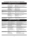
See application decal inside door of
wire feed compartment for proper
heat settings.
NOTE: These settings are general
guidelines only. Heat setting may vary
according to welding conditions and
materials.
6. Rotate Wire Speed Control to
setting number 5. Then adjust as
needed after test weld is completed.
7. Plug input cord into a proper
voltage receptacle with proper
circuit capacity (20 amps minimum).
8. Switch welder ON.
9. Verify that the wire is extended
1/4” from the contact tip. If not,
squeeze trigger to feed additional
wire, then release trigger, and then
cut wire to proper length.
!
WARNING
Operation
MANUAL
Shielding Gas
Installation (Continued)
www.chpower.com
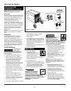
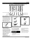
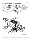
Figure 9 - Hookup
ARGON OR
ARGON MIX
INSTALLATION
CO
2
INSTALLATION
OR
CO
2
Adapter
Cap