


5
WG4000
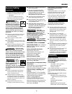
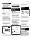
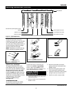
9. Carefully slip contact tip over wire
and screw it into torch neck. Install
nozzle by turning clockwise (See
Figure 5). Cut wire off approximately
1/4” from end of nozzle.
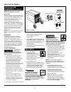
POLARITY
Polarity must be set to match the type
of welding process you wish to use.
MIG wire welding with bottled
shielding gas uses DCEP (DC electrode
positive). Flux-core wire welding with
no gas bottle requires DCEN (DC
electrode negative).
The WG4000 features easy-change
polarity posts located inside the top
section, next to the wire drive deck.
The positive (+) post is farthest from
the drive deck and has a red knob and
base. The negative post is closest to the
drive deck and has a black knob and
base.
Both leads have spade ends with holes
to go over the polarity posts. Turn the
polarity knob counterclockwise to
remove. Slip the end of the
appropriate lead over the post. Then
replace the polarity knob on the post
and tighten securely, turning clockwise.
These connections must be tight to
prevent overheating.
DUTY CYCLE / THERMOSTATIC
PROTECTION
Welder duty cycle is the percentage of
actual weld time that can occur in a ten
minute interval. For example, at a 10%
duty cycle, actual welding can occur for
one minute. Then the welder must cool
for nine minutes.
Internal components of this welder are
protected from overheating with an
automatic thermal switch. A yellow
lamp is illuminated on the front
panel if the duty cycle is exceeded.
Welding operations may continue
when the yellow lamp is no longer
illuminated.
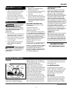
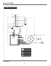
MODEL WT1000
1. Remove lens retainer from face shield
with a regular screwdriver by prying
against shield and post of lens
retainer.
2. Remove protective film covering from
both sides of each lens cover. Put one
clear lens cover on each side of the
shaded lens. Place these three lenses
together in face shield and secure
with lens retainer. The lens retainer
should snap into second notch in face
shield.
3. Position one of the holes in
adjustment arm over the pins which
are located in the ear area of face
shield. These adjustment arms control
the closeness of fit and can be easily
repositioned if necessary.
4. Position headgear inside face shield.
Assemble helmet by inserting stud
screw through headgear and shield
into tension nut as shown. Do not
tighten tension nut completely.
5. Trial fit the welding helmet. Adjust
headgear ratchet band to a
comfortable position and lower face
shield. If shield is too far or too close
to face, use a different hole in
adjustment arm. Adjust tension nuts
so that helmet can be easily lowered
over the face by nodding the head.
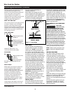
1. Cut two plastic bolts and one nut
from handle. Trim excess plastic to
remove sharp edges.
2. Insert handle into slot and rotate 90
degrees to align handle stud with
hole in shield. Secure stud with
plastic nut.
3. Fold the top into position and then
one of the sides. Snap the two pins
into the holes. Press until you hear an
audible click, assuring complete
assembly. Repeat for the other side.
4. Install the shaded lens and secure
with the two plastic bolts. Tighten
securely, but do not overtighten as
this may damage the lens.
NOTE: If you have never welded before
or have little experience, a full-face
helmet is recommended. Both hands
are needed to stabilize and control the
angle and arc length of the torch.
Improper handling
and maintenance of
compressed gas cylinders and
regulators can result in serious injury
or death! Always secure gas cylinders
to the tank bracket kit, a wall or other
fixed support to prevent the cylinder
from falling over. Read, understand,
and follow all the warnings relating to
compressed gases and equipment
hazards in the safety instructions.
!
DANGER
Assembly
(Continued)
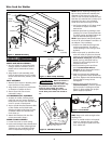
Figure 7
Headgear
Face Shield
Shaded Lens
Clear Lens Cover (2)
Post
Lens Retainer
Adjustment
Arm (2)
Tension Nut (2)
Stud Screw (2)
Welding Helmet
Assembly
(PROMOTIONAL MODELS ONLY)
www.chpower.com
Contact Tip Markings
Wire Size mm
.024” or .6
.030” or .8
.035” or .9
.040” or 1.0
Torch Work
Mig + —
Flux —
+
Figure 6
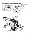
Shielding Gas
Installation
Work Cable
Torch
Cable
Handshield
Assembly
Figure 8