


Assembly
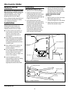
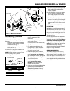
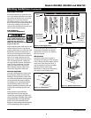
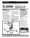
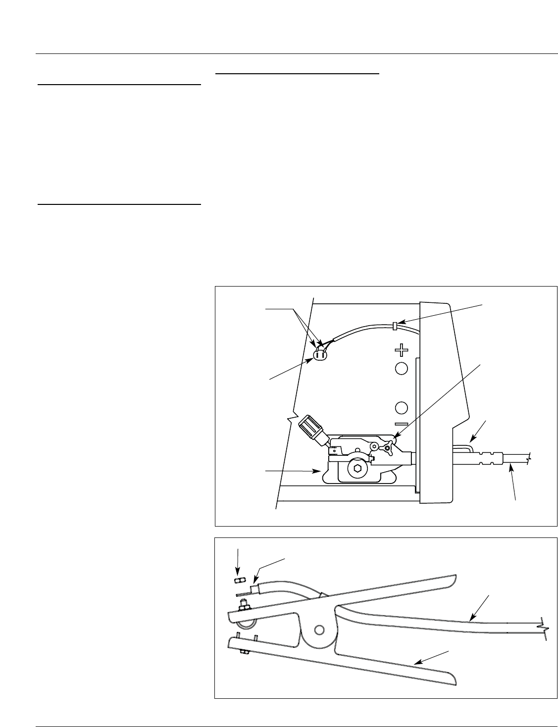
TORCH INSTALLATION (See Fig. 2)
1. Make sure unit is off and unplugged.
2. Feed the connectors for the torch
switch through the hole in the control
panel. These leads are to be fed up
over the polarity studs and through the
hanger on the center wall.
3. Insert the brass torch connector
through the hole in the control panel
and into the drive deck. Make sure the
connector is inserted fully into the
drive deck. Loosen the torch clamp
knob a few turns if the connector will
not insert fully. Tighten the torch
clamp knob securely after the brass
torch connector is fully inserted.
Wire Feed Arc Welder
General Safety
(Continued)
Safe Practices For Occupational And
Educational Eye And Face Protection
ANSI Standard Z87.1, from American
National Standards Institute, 1430
Broadway, New York, NY 10018
Refer to Material Safety Data Sheets and
manufacturers instructions for metals,
wire, coatings and cleaners.
Installation
LOCATION
Selecting the proper location can
significantly increase performance,
reliability and life of the arc welder.
● For best results locate welder in a
clean and dry environment. Dust
and dirt in the welder retain
moisture and increase wear of
moving parts.
● Place welder in an area with at least
twelve inches (305 mm) of ventilation
space at both the front and rear of
unit. Keep all obstructions out of this
ventilation space.
● Store welding wire in a clean, dry
location with low humidity to
prevent oxidation.
● Use a properly grounded receptacle
for the welder and ensure welder is
the only load on power supply
circuit. Refer to chart on page 1 for
correct circuit capacity.
● Use of an extension cord is not
recommended for electric arc welding
machines. Voltage drop in the
extension cord may significantly
degrade performance of the welder.
4. Connect the torch switch connectors to
the two 1/4" terminals in the center
wall. Polarity is not important. Make
sure these wires do not interfere with
the polarity studs or drive deck.
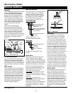
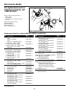
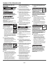
WORK CLAMP INSTALLATION
(See Fig. 3)
1. Remove one hex nut from work clamp.
2. Slide welding cable with ring
connector through hole in work clamp.
3. Attach ring connector to work clamp
with hex nut removed in step 1.
4
www.chpower.com
Work clamp
Welding cable
Ring connector
Hex Nut
Figure 3 - Clamp Installation
Hanger
Torch switch leads
Torch clamp knob
Torch switch
connectors
Drive deck
Torch switch
terminals
Torch
Figure 2 - Torch Installation