


Assembly (Continued)
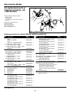
WIRE INSTALLATION
NOTE: Before installing welding wire,
be sure:
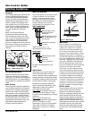
a. Diameter of welding wire matches
groove in drive roller on wire feed
mechanism (See Fig. 4).
b. Wire matches contact tip in end of
torch (See Fig. 5).
A mismatch on any item could cause the
wire to slip and/or bind.
NOTE: Always maintain control of loose
end of welding wire to prevent
unspooling.
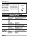
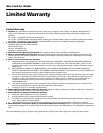
7. Unscrew nozzle and contact tip from
end of welding torch (See Figure 5).
Plug welder into a proper power
supply receptacle.
8. Turn on welder and set wire speed
to 10. Activate torch trigger until
wire feeds out past the torch end.
Turn welder off.
9. Carefully slip contact tip over wire,
screw tip into torch end and reinstall
nozzle (See Figure 5). Cut wire off
approximately 1/4 inch from nozzle
end.
DUTY CYCLE / THERMOSTATIC
PROTECTION
Welder duty cycle is the percentage of
actual weld time that can occur in a ten
minute interval. For example, at a 20%
duty cycle, actual welding can occur for
two minutes, then the welder must cool
for eight minutes.
Internal components of this welder are
protected from overheating with an
automatic thermal switch. A red lamp is
illuminated on the front panel if the
duty cycle is exceeded. Do not switch
unit off. This will allow the internal fan
to cool the unit quickly. Welding
operations may continue when the red
lamp is no longer illuminated.
OVERLOAD PROTECTION
The welder is equipped with a circuit
breaker which protects the machine if
the maximum output is exceeded, such as
when the output is short-circuited. The
circuit breaker button will extend out
when tripped. Manually push the button
in to reset.
Models WG3080, WG3090 and WG4130
5
www.chpower.com
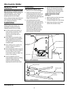
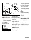
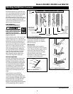
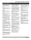
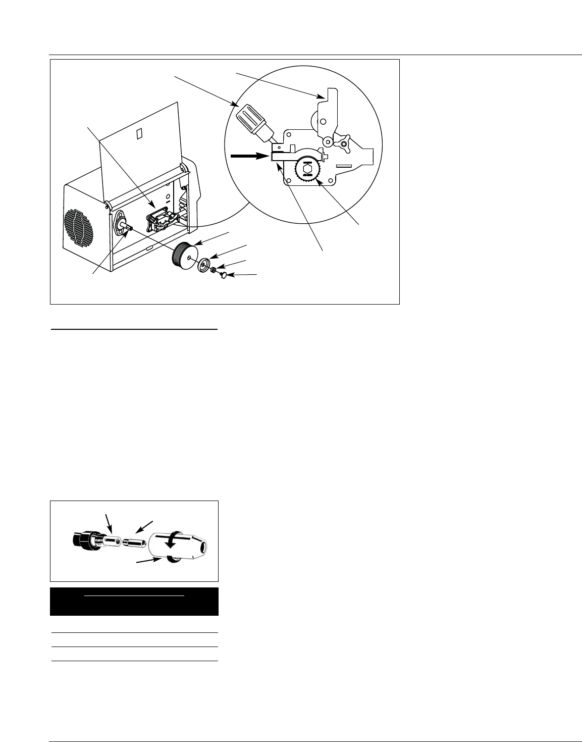
1. Verify unit is off and open door
panel to expose wire feed
mechanism.
2. Remove the spool lock by pushing in
and rotating 1/4 turn
counterclockwise. Then remove lock,
spring and retainer.
3. Flip tensioning knob down and
swing arm up on drive mechanism.
This allows initial feeding of wire
into torch liner by hand.
4. Install wire spool onto spindle so
wire can come off spool bottom of
spool. Do not cut the wire loose
yet. Install spool retainer, spring and
lock by pushing in and turning lock
1/4 rotation clockwise.
5. Hold wire and cut the wire end from
spool. Do not allow wire to
unravel. Be sure end of wire is
straight and free of burrs.
6. Feed wire through wire guide, over the
groove in drive roller and back into
wire guide. Flip swing arm down and
tension knob up. Adjust tension by
rotating tension knob.
Contact Tip Markings
Mark Wire Size
0.6 mm .024"
0.8 mm .030"
0.9 mm .035"
Torch Diffuser
Contact Tip
Nozzle
Figure 5 - Torch Nozzle
Spindle
Welding wire
Lock
Spring
Retainer
Tension knob
Wire guide
Swing arm
Drive deck
Drive
roller
Figure 4 - Weld Wire Installation