


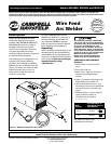
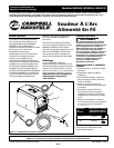
Models WG3080, WG3090 and WG4130
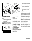
Operation
1. Be sure to read, understand
and comply with all
precautions in the General
Safety Information section.
Be sure to read entire
“Welding Guidelines” section before
using this equipment.
2. Turn welder off.
3. Verify surfaces of metals to be joined
are free from dirt, rust, paint, oil,
scale or other contaminants. These
contaminants make welding difficult
and cause poor welds.
All persons operating this equipment or
in the area while equipment is in use
must wear protective welding gear
including: eye protection with proper
shade, flame resistant clothing, leather
welding gloves and full foot protection.
If heating, welding or cutting
galvanized, zinc plated, lead,
or cadmium plated materials,
refer to the General Safety
Information Section for instructions.
Extremely toxic fumes are created when
these metals are heated.
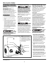
4. Connect work clamp to work piece or
workbench (if metal). Make sure
contact is secure. Avoid surfaces with
paint, varnish, corrosion or non-
metallic materials.
5. Rotate Wire Speed Control to setting
per decal inside wire feed
compartment, then adjust as needed
after test.
6. Plug power cord into a proper
voltage receptacle with proper circuit
capacity (see circuit requirements on
Page 1).
7. Switch welder on to desired heat
setting per decal inside wire feed
compartment, then adjust as needed
after test.
NOTE: These settings are general
guidelines only. Heat setting may vary
according to welding conditions and
materials.
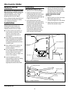
8. Verify wire is extended 1/4" from
contact tip. If not, squeeze trigger to
feed additional wire, release trigger,
turn welder off, and cut wire to
proper length. Then, switch back on
to desired heat setting.
9. Position torch near work piece, lower
welding helmet by nodding head or
positioning the hand shield, and
squeeze torch trigger. Adjust heat
setting and wire speed as needed.
10. When finished welding, turn welder
off and store properly.
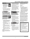
Maintenance
Disconnect power supply and turn
machine off before inspecting or
servicing any components. Keep wire
compartment cover closed at all times
unless wire needs to be changed.
BEFORE EVERY USE:
1. Check condition of weld cables and
immediately repair or replace any
cables with damaged insulation.
2. Check condition of power cord and
immediately repair or replace any
cord if damaged.
3. Inspect the condition of the torch
contact tip and nozzle. Remove any
weld slag. Replace torch contact tip or
nozzle if damaged.
Do not
operate
this welding machine with cracked or
missing insulation on welding cables,
torch or power cord.
EVERY 3 MONTHS:
1. Replace any unreadable safety labels
on the welder.
2. Use compressed air to blow all dust
and lint from ventilation openings.
3. Clean wire groove on drive roller.
Remove drive roller and use a small
wire brush to clean. Replace if worn
or damaged.
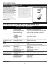
Consumable and Wear Parts
The following parts require replacement:
• Wire feed drive roller
• Wire guide
• Torch liner
• Nozzle/contact tips
• Wire - This welder will accept either 4"
or 8" diameter spools. Flux-Cored
welding wire is susceptible to
moisture and oxidizes over time, so it
is important to select a spool size that
will be used within approximately 6
months. For mild steel welding, AWS
ER70S6 solid wire or AWS E71T-GS
Flux-Cored wire is recommended.
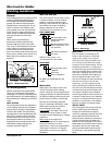
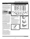
CHANGING WIRE SIZES
This welder is setup for .030" (0.8 mm)
wire. If a different wire size is used, the
wire feed drive roller and contact tip
may need changing. There are two
grooves in the drive roller. The small
groove is for .024" (0.6 mm) MIG wire
and the large groove is for .030 - .035"
(0.8 - 0.9 mm) flux core and MIG wire.
Rotate the tension knob down and
swing arm up and flip the drive roller
to choose the correct groove. Optional
drive rollers for other wire sizes are
available (See parts breakdown). The
contact tip should also match the wire
diameter used. The tip diameter is
marked on the contact tip in inches
and/or millimeters.
7
www.chpower.com
MANUAL
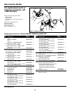
Supply Cable Replacement
1. Verify that welder is OFF and
power cord disconnected.
2. Remove welder side panel to
expose switches.
3. Disconnect the power cord leads
per the diagram inside the unit.
4. Disconnect the ground wire
connected to welder base.
5. Loosen the cord strain relief
screws and pull cord out of strain
relief.
6. Install new cord in reverse order
per the diagram inside the unit.