If heating, welding, or
cutting materials that are
galvanized, zinc plated, lead,
or cadmium plated refer to the General
Safety Information Section for
instructions. Extremely toxic fumes are
created when these metals are heated.
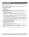
4 . Connect the work clamp to the
work piece. Make sure the contact is
on bare metal and not obstructed
by paint, varnish, corrosion, or non-
metallic materials.
5 . Insert the exposed part of the
electrode rod (the end with no flux)
into the jaws of the electrode
h o l d e r .
The electrode
holder and rod are
electrically “live” (current potential)
when the welder is on.
Grounding against
any metallic
surface may produce an arc which could
cause sparks and damage eyesight.
6 . Hold the electrode away from the
grounded work piece or
workbench. Turn on the welder to
either High or Low. Refer to the
following chart for proper output
s e t t i n g .
7 . Position the electrode to begin
weld, lower the welding helmet or
position the hand shield, and strike
an arc. Adjust output setting as
n e e d e d .
8 . When finished welding, turn welder
off and store properly.
4
Shielded Metal Arc Welder
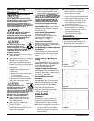
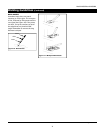
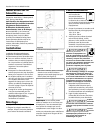
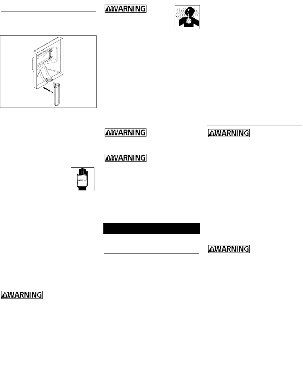
3 . To attach the handle, place shield on
a flat surface and press handle into
place (See Figure 5).
NOTE: If you have never welded before
or have little experience, a full face
helmet is recommended. Both hands
are needed to stabilize and control the
angle and arc length of the electrode.
O p e r a t i o n
1 . Be sure to read,
understand, and comply
with all precautions in
the General Safety
Information section. Be sure to read
the entire section entitled Welding
Guidelines prior to using this
e q u i p m e n t .
2 . Turn welder off and plug into
appropriate receptacle:
115v-15 amp - Low
115v-20 amp - High
3 . Verify that the surfaces of metals to
be joined are free from dirt, rust,
paint, oil, scale or other contaminants.
These contaminants make welding
difficult and cause poor welds.
All persons
operating this
equipment or in the area while
equipment is in use must wear protective
welding gear including: eye protection
with minimum shade 10 lens, flame
resistant clothing, leather welding
gloves, and full foot protection.
DUTY CYCLE / THERMOSTATIC
P R O T E C T I O N
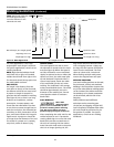
Welder duty cycle is the percentage of
actual weld time that can occur in a
ten minute interval. For example, at a
10% duty cycle, actual welding can
occur for one minute, then the welder
must cool for nine minutes.
Internal components of this welder are
protected from overheating with an
automatic thermal switch. A yellow
lamp is illuminated on the front panel
if the duty cycle is exceeded. Welding
operations may continue when the
yellow lamp is no longer illuminated.
M a i n t e n a n c e
Disconnect power
supply and turn
machine off before inspecting or
servicing any components.
Before every use:
1 . Check condition of weld cables and
immediately repair or replace any
cables with damaged insulation.
2 . Check condition of power cord and
immediately repair or replace any
cord if damaged.
3 . Check condition of electrode holder
insulating pieces and immediately
replace cracked or missing
insulators. Verify that all fasteners
are tight and insulated.
Do not operate this
welding machine
with cracked or missing insulation on
welding cables, electrode holder, or
power cord.
Every 3 months:
Replace any unreadable labels on the
welder. Use compressed air to blow all
dust and lint from the ventilation
o p e n i n g s .
w w w . c h p o w e r . c o m
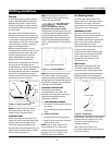
Electrode Output
Diameter Setting
1/16 in. (1.6 mm) L o w
5/64 in. (2 mm) H i g h
Figure 5
Assembly ( C o n t i n u e d )


