


SKU 42933 For technical questions, please call 1-800-444-3353. Page 10
REV 01c
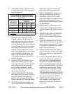
SPECIFICATIONS
Power
Requirements
120 V~, 60 Hz, 1-ph
20.9 A (start); 6.9 A (load); 1330 W
Motor
1-3/4 HP, 4200 spindle RPM,
electric brake
Saw Blade 8-1/4” (dia.)
Arbor 5/8”
Crosscut Distance 11” (maximum)
Rip Cut Distance 20” (maximum)
Depth of Cuts 45°: 2”; 90°: 2-1/8”
Bevel Index Stops 0, 45, 90°
Mitre Index Stops Left and right: 0, 15, 30, 45, and 60°
Table Size 15-1/16 x 27-5/8 x 3/4”
Accessories Blade Replacement: Item # 43204
Note: Performance of this tool may vary
depending on variations in local line
voltage. Extension cord usage may
also affect tool performance.
UNPACKING
When unpacking, check to make sure
that all the parts are included. Refer to the
Parts List and Assembly Drawing at the
end of this manual. If any parts are miss-
ing or broken, please call Harbor Freight
Tools at 1-800-444-3353 as soon as pos-
sible.
INSTALLATION
During the assembly and installation
procedure, you may have to refer to the
Parts List and Assembly Drawings located
at the end of this manual.
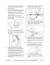
Secure the Radial Arm Saw to a solid 1.
bench top (or table) by bolting (or
clamping) the saw frame down to the
bench top.
The workbench must not be able to •
slide or tip over. Afx to oor if nec-
essary.
Position the Radial Arm Saw (or saw •
and bench) to slope slightly to the
rear so the radial arm carriage will
not roll forward due to gravity.
The workbench should be of the ap-•
propriate length and width to allow
the operator to stand aside of the
saw blade, whatever position the
saw blade is in.
The work area should have ade-•
quate, overhead, non-glare lighting.
Lock the radial arm carriage before •
moving the unit.
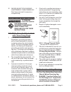
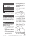
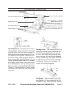
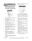
2. Turn the Base (152) assembly upside
down. Attach Table A (127) squarely
to the Base assembly using the four
cross-head Tapping Screws (165).
Attach the table stabilizer Stands to 3.
both sides of the Base using four Hex
Nuts (82), Washers (149), and Round
Head Bolts (148).
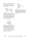
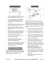
Place the Table and Base assem-4.
bly on the workbench, right side up.
Secure to the workbench with nuts,
bolts, and washers (not supplied).
5. Position Table B (126) and Table C
(125), and the rip fence (guide) and