


SKU 42933 For technical questions, please call 1-800-444-3353. Page 14
ADJUSTMENTS
The following checks, and possible adjust-
ments, should be done in the order listed
before beginning operation.
WARNING: For safety, unplug the line
cord to the Radial Arm Saw.
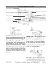
Tables A (127), B (126), and C (125) 1.
are checked for straightness at the
factory.
However, changes in humidity can
slightly alter the condition of the
wood. With the Screw Clamps (131)
tightened, use a straight edge or
framing square to check for atness
and squareness. Sand down any high
spots using ne sandpaper.
Check for Arm tightness on the Col-2.
umn (132). If loose, tighten Bolt (115).
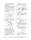
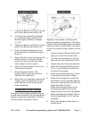
3. Check the crosscut travel of the Saw
Blade for squareness.
- Lock or tighten all adjustment levers
and knobs.
- Lower the Arm until it just clears the
Table A front.
- Place a framing square so it just
touches a tooth of the Saw Blade.
- Mark this location with a pencil on
the table and draw a straight line us-
ing the square.
- Check that the Saw blade follows
this line from front to back.
If the Saw Blade moves to the right
or left side of the line as it travels the
entire length of the Arm, loosen the
Screw Clamps (137) and lightly tap
on the Table left or right side until
there is full travel alignment. Tighten
the Screw Clamps again.
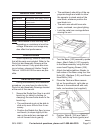
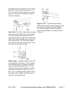
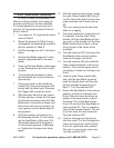
4. Check that the Saw Blade is square
to Table A.
- Place a framing
square on Table A
so that the square
is at on the Saw
Blade (not touching
teeth).
- If there is no gap between the
square and the Saw Blade, no adjust-
ment is necessary.
- If the square does not touch the
Saw Blade evenly (with the square
at on the Table A), loosen the Bevel
Lock Knob (71) and adjust the motor
until the gap between Saw Blade and
the square is eliminated.
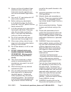
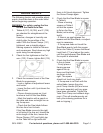
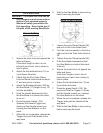
5. Check that the Saw Blade is square
to the rip fence.
- Firmly place a
framing square
against the rip
fence and the blade
as shown to the
right. The square
should not touch any teeth.
- If the square is not ush with the
entire blade, loosen the yoke
pivot Clamp Handle (66) and move
the motor assembly until any gaps
have been eliminated. Tighten the
Yoke Pivot Clamp and recheck align-
ment. (This will simultaneously set
both yoke indexing positions for in
and out ripping.)