


Page 6SKU 67102 For technical questions, please call 1-800-444-3353.
Grounding prong in plug is connected 2.
through green wire inside cord to
grounding system in tool. Green wire
in cord must be only wire connected
to tool’s grounding system and must
never be attached to “live” terminal.
(See 3-Prong Plug and Outlet.)
Tool must be plugged into appropriate 3.
outlet, properly installed and
grounded in accordance with codes
and ordinances. Plug and outlet
should look like preceding illustration.
(See 3-Prong Plug and Outlet.)
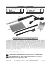
Extension Cords
Grounded1. tools require a three wire
extension cord. Double Insulated
tools can use either a two or three
wire extension cord.
As distance from supply outlet 2.
increases, use a heavier gauge
extension cord. Using extension
cords with inadequately sized wire
causes a drop in voltage, resulting
in loss of power and possible tool
damage. The smaller the gauge
number of wire, the greater capacity
of cord. For example, a 14 gauge
cord can carry a higher current than a
16 gauge cord. (See Table A.)
When using more than one extension 3.
cord to make up the total length,
make sure each cord contains at
least the minimum wire size required.
(See Table A.)
If using extension cord for more than 4.
one tool, add nameplate amperes
and use sum to determine required
minimum cord size. (See Table A.)
If using extension cord outdoors, 5.
make sure it is marked with “W-
A” (“W” in Canada) to indicate it is
acceptable for outdoor use.
Make sure extension cord is properly 6.
wired and in good electrical condition.
Always replace damaged extension
electrician before using it.
Protect extension cords from sharp 7.
objects, high heat, and wet areas.
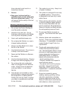
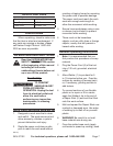
RECOMMENDED MINIMUM WIRE
GAUGE FOR EXTENSION CORDS*
(120/240 VOLT)
NAMEPLATE
AMPERES
(at full load)
EXTENSION CORD
LENGTH
25’
50’
75’
100’
150’
0 – 2.0 18 18 18 18 16
2.1 – 3.4 18 18 18 16 14
3.5 – 5.0 18 18 16 14 12
5.1 – 7.0 18 16 14 12 12
7.1 – 12.0 18 14 12 10 -
12.1 – 16.0 14 12 10 - -
16.1 – 20.0 12 10 - - -
TABLE A
* Based on limiting the line
voltage drop to ve volts at
150% of the rated amperes.
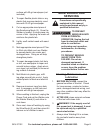
Symbology
Double Insulated
Canadian Standards Association
V~
Volts Alternating Current
A
Amperes
n
0
xxxx/min.
(RPM)