


SKU 67119 For technical questions, please call 1-800-444-3353. Page 13
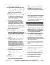
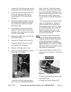
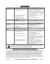
Loosen the Thumb Screw so that the 1.
Depth Stop Bar (30) can slide freely.
Rotate the Adjusting Knob (26) until 2.
the Depth Adjusting Bolt (29) pro-
trudes about 1/4” from the Depth
Stop Bar.
Rotate the Depth Stop Bar to the left 3.
so that the indexing mark along the
top of the Bar is visible from under
the Pointer (28).
Hold the Bar and rotate the Adjust-4.
ing Knob until the Zero mark along
the base of the adjusting Knob aligns
with the indexing line.
Rotate the Depth Stop Turret (67) to 5.
the lowest setting.
Loosen the Plunge Lock Lever (32).6.
Lower the Router body until the bit 7.
just touches the workpiece.
Tighten the Plunge Lock Lever.8.
Use one of the following two ways to 9.
adjust the router depth:
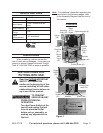
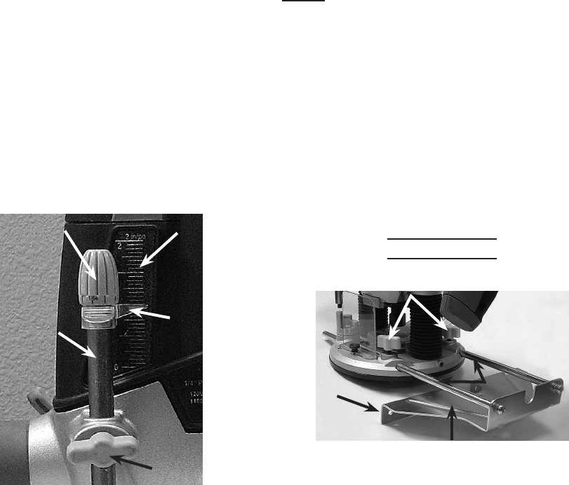
Increment Guide
Pointer
(28)
Adjusting
Knob (26)
Depth
Stop
Bar
(30)
Thumb Screw
Figure 4
• Position the Depth Adjusting Bolt
(29), so that it is touching the Depth
Stop Turret (67). Slide the Pointer
(28) to zero on the Increment Guide,
then raise the Depth Stop Bar to the
desired height using the Pointer and
the Increment Guide. Tighten the
Thumb Screw to hold the Stop Bar in
place.
Or, using a piece of wood the thick-•
ness of the desired cut, place the
piece of wood on the Lowest level
of the Depth Stop Turret (67). Adjust
the Depth Stop Bar (29) so that the
Depth Stop Bolt (29) rests on the
piece of wood and tighten in place
with the Thumb Screw.
Note: For marginal depth adjustments,
raise the Depth Adjusting Bolt (29)
(located inside the Depth Stop Bar)
in ne increments by turning the
Adjusting Knob (26) to set the exact
desired depth of cut. Use the Pointer
(28) along with the increment guide to
help make the adjustment.
Loosen the Plunge Lock Lever and 10.
allow the router to return to its original
position.
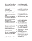
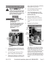
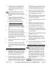
Edge Guide
Thumb Screws (81)
Edge Guide
Fence
Bars
Figure 5
To attach the Edge Guide when mak-
ing straight cuts:
Loosen the Thumb Screws (81).a.