


1-2
Cisco Secure Router 520 Series Hardware Installation Guide
OL-12892--01
Chapter 1 Product Overview
Router Models
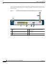
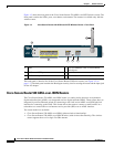
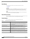
Figure 1-1 shows the front panel of the Cisco Secure Router 520 Ethernet-to-Ethernet wireless router.
The front panel contains the LEDs, ports, reset button, and antenna. The antenna is available only with
the wireless router.
Figure 1-1 Cisco Secure Router 520 Ethernet-to-Ethernet Wireless Router—Front Panel
Cisco Secure Router 500 Series
231358
5
4
3
6
2
1
1 LEDs 2 Four 10/100BASE-T RJ-45 Fast Ethernet
switch ports
3 10/100BASE-T RJ-45 WAN Fast Ethernet
port
4 Reset button
5 RJ-45 console port 6 Antenna (wireless router only)