


A-2
Cisco Secure Router 520 Series Hardware Installation Guide
OL-12892-01
Appendix A Specifications
LAN Port Pinouts
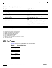
LAN Port Pinouts
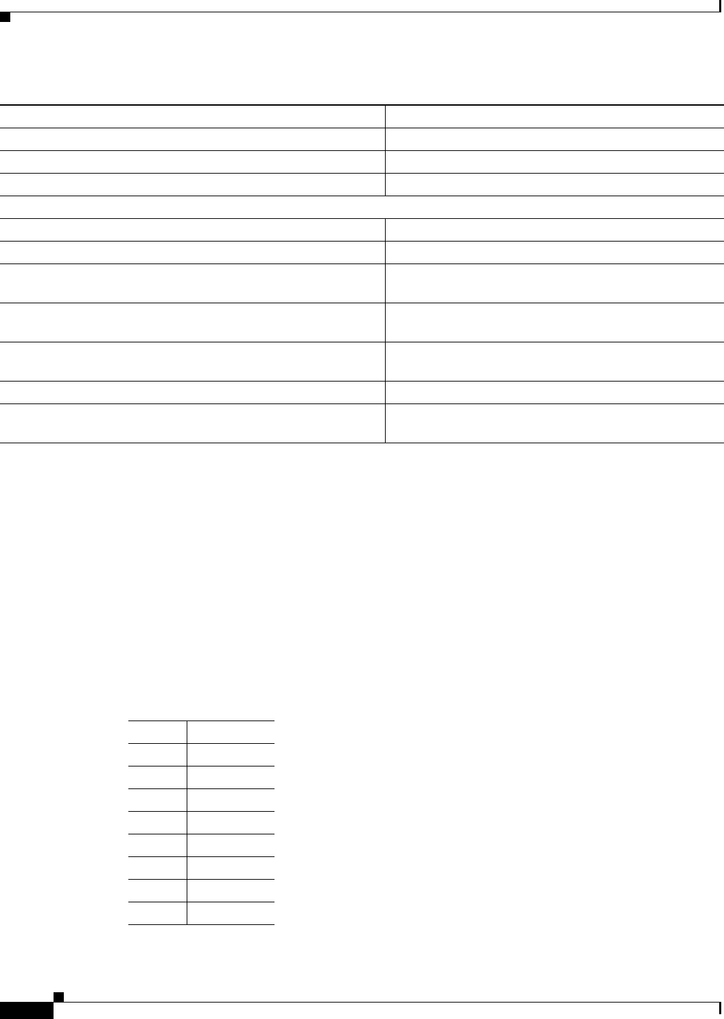
Table A-2 provides pinouts for the Ethernet LAN port on the routers.
Ta b l e A-2 Ethernet LAN Port Pinouts
Pin Function
1 RX+
2 RX–
3 TX+
4 Unused
5 Unused
6 TX–
7 Unused
8 Unused
Frequency 50 to 60 Hz
Power output 26 W maximum
Output voltages 5 V and 12 V
Integrated 802.11b/g Radio Module
Radio technology IEEE 802.11b and 802.11g standard compliant
Operating frequency 2412 to 2484 MHz ISM
1
band
Modulation schemes OFDM
2
, DQPSK
3
, DBPSK
4
16 QAM
5
, 64 QAM, and
CCK
6
Number of channels 11 channels for the U.S., 13 channels for Europe, 14
channels for Japan
Data rate 54 Mbps with fallback rates of 48, 36, 24, 18, 12, 9, and
6
Mbps
Media access protocol CSMA/CA
7
with ACK
8
Power consumption (typical) 500 mA 3.3V at transmit mode, 320 mA/3.3V at receive
mode
1. ISM = Industrial, Scientific, and Medical.
2. OFDM = orthogonal frequency-division multiplexing.
3. DQPSK = differential quaternary phase shift keying.
4. DBPSK = differential binary phase shift keying.
5. QAM = quadrature amplitude modulation.
6. CCK = complementary code keying.
7. CSMA/CA = carrier sense multiple access with collision avoidance.
8. ACK = acknowledgement.
Table A-1 Router Specifications (continued)
Description Design Specification