


14
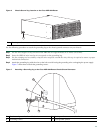
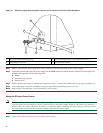
Step 3 Insert an Ethernet RJ-45 cable into the MGMT ETHERNET port.
Step 4 Insert the other end of the RJ-45 cable to your management device or network.
Step 5 Configure to a fixed speed through the command line interface (CLI) commands.
Connect the Shared Port Adapter Cables
The instructions for connecting the cables for the shared port adapter installed in the Cisco ASR 1004 Router are contained in
the Cisco ASR 1000 Series Aggregation Services Routers SPA and SIP Hardware Installation Guide.
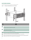
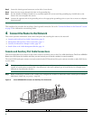
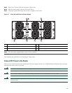
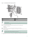
Install Cables in the Cable-Management Bracket
No specific card level cable management will be provided on the SIP carrier cards. SPAs utilize the SPA cable management
brackets that are provided with each SPA as part of their accessory kits. Cables coming off the front side of the SPAs and SIPs
utilize the chassis level cable management brackets provided on the chassis rack mount brackets (see Figure 9).
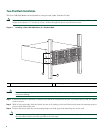
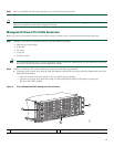
To secure shared port adapter interface cables and input or output cables connected to the Cisco ASR 1004 Router, follow these
steps:
Step 1 When installing the network interface cables, route the cables up to and through the cable-management bracket ‘U’
device. If you are using very thin cables that slip through the bracket openings, insert nylon cable ties through the holes
in the bracket and wrap them around the cables to secure them.
Step 2 Route the excess cable out through either end of the bracket, coil it, and secure it to the rack using nylon cable ties or
some other mode of attachment.
Step 3 It might be necessary to bundle longer cables to avoid tangling them. Do this at the cable-management bracket or at
the rack, but leave enough slack in the cables to remove processor modules and change cables as required. Also, do not
block the power supply air vents with cables.
This completes the procedure for installing the cables using the cable-management bracket.
Proceed to the “Start the System” section on page 14 to complete the installation.
5 Start the System
Before you start the system, you must connect power to it.
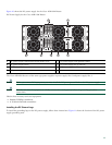
Connect AC Power to the Router
This section provides information about installing an AC power supply in the Cisco ASR 1004 Router.
Warning
Never install an AC power module and a DC power module in the same chassis.
Statement 1050
.
Warning
Installation of the equipment must comply with local and national electrical codes.
Statement 1074
Step 1 Insert an AC power supply in power supply Slot 0 or power supply Slot 1 until it is full seated.
Step 2 Tighten the captive installation screws.