


18
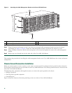
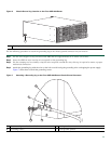
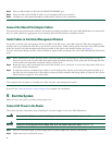
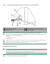
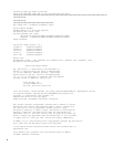
Figure 11 DC Power Supply Grounding Stud Location and Connection on the Cisco ASR 1004 Router
Step 1 Make certain that the chassis ground is connected before you begin installing the DC power supply.
Step 2
Locate the ground stud on the DC power supply for the GND connection which must be installed first and replace the
ground stud components in the following order:
b. Washer
c. Grounding lug with wire
d. Kepnut screw
Step 3 Tighten the Kepnut screw to complete the installation. Figure 11 shows the installed DC power supply ground stud.
Step 4 Ground the other end of the grounding wires to an appropriate grounding point at your site.
Step 5 Repeat Steps 2 through Step 4 on the second DC power supply.
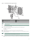
Wiring the DC-Input Power Source
Note The color coding of the DC-input power supply leads depends on the color coding of the DC power source at your site.
Typically, green or green/yellow is used for ground (GND) on the power supply. Negative –48V black is on negative (–)
terminal and red is used for RTN on the positive (+) terminal. Make certain the lead color coding you choose for the
DC-input power supply matches lead color coding used at the DC power source.
Step 1 Make sure the power switch circuit breaker is in the Off position.
Step 2 Locate and remove the plastic cover from the terminal block.
1
DC power supply grounding stud
3
DC power supply chassis grounding stud location
2
Grounding stud screws
4
Earth ground symbol
280034
3
4
2
1